


v
SPCN
card
(see
symbolic
FRU
in
the
failing
unit
(first
frame
with
a
failure
indication)
v
SPCN
card
(see
symbolic
FRU
in
the
preceding
unit
in
the
string
v
SPCN
optical
adapter
A
in
the
preceding
unit
in
the
string
v
SPCN
optical
adapter
B
in
the
failing
unit
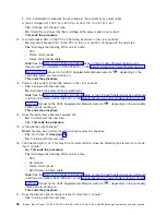
v
SPCN
optical
cables
C
between
the
preceding
unit
in
the
string
and
the
failing
unit
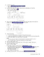
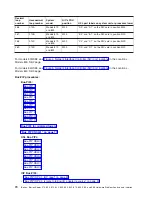
(A)
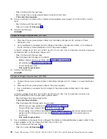
SPCN
Optical
.-----
(C)
SPCN
Adapter
----.
|
Optical
Cables
|
|
|
|
.--
(B)
SPCN
.---------.
|
|
|
Optical
|
System
|
|
|
|
Adapter
|
Unit
|
V
|
V
|
J15
|
.-.
V
.-.
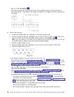
’----.----’
|
+------------+
|
|
|
+------------+
|
.----’----.
.-------’-+
.-------’-+
.---------.
|Sec
J15
|
|
Sec
J16|
|Sec
J15|
|
Sec
|
|Unit
J16+-+J15
Unit
|
|Unit
J16+-+J15
Unit
|
|
1
|
|
2
|
|
3
|
|
4
|
’---------’
’---------’
’---------’
’---------’
^
|
|
’---
Failing
Unit
This
ends
the
procedure.
24.
Does
the
SPCN
frame-to-frame
cable
coming
from
the
system
unit
connect
to
J15
on
the
secondary
unit
(where
the
power
on
light
is
off
or
the
unit
control
panel
displays
a
power
reference
code
of
1xxx
xxxx)?
v
No
:
Correct
the
connection
by
connecting
the
SPCN
frame-to-frame
cable
coming
from
the
system
unit
to
J15
of
the
secondary
unit.
This
ends
the
procedure.
v
Yes
:
Continue
with
the
next
step.
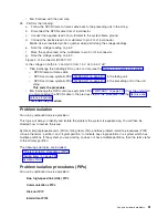
25.
Perform
the
following:
a.
Power
off
the
system.
b.
Disconnect
the
SPCN
frame-to-frame
cable
from
J15
connector
of
the
first
unit
that
cannot
become
powered
on.
c.
Connect
the
negative
lead
of
a
multimeter
to
the
system
frame
ground.
d.
Connect
the
positive
lead
of
the
multimeter
to
pin
2
of
the
SPCN
cable.
Note
:
Use
an
insulated
probe
or
jumper
when
performing
the
voltage
readings.
e.
Note
the
voltage
reading
on
pin
2.
f.
Move
the
positive
lead
of
the
multimeter
to
pin
3
of
the
SPCN
cable.
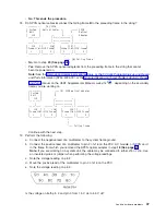
g.
Note
the
voltage
reading
on
pin
3.
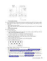
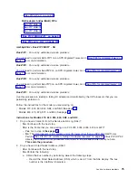
Figure
8.
SPCN
cable
connector.
(RV2A180-1)
Is
the
voltage
on
both
pin
2
and
pin
3
from
1.5
V
dc
to
5.5
V
dc?
v
Yes
:
Exchange
the
following
FRUs,
one
at
a
time
(see
–
SPCN
card
(see
symbolic
FRU
in
the
failing
unit.
–
SPCN
card
(see
symbolic
FRU
in
the
preceding
unit
in
the
unit
string.
–
SPCN
frame-to-frame
cable.
This
ends
the
procedure.
60
iSeries:
iSeries
Server
270,
800,
810,
820,
825,
830,
840,
870,
890,
SB2,
and
SB3
Hardware
Problem
Analysis
and
Isolation
Содержание iSeries Series
Страница 2: ......
Страница 504: ...492 iSeries iSeries Server 270 800 810 820 825 830 840 870 890 SB2 and SB3 Hardware Problem Analysis and Isolation...
Страница 508: ...496 iSeries iSeries Server 270 800 810 820 825 830 840 870 890 SB2 and SB3 Hardware Problem Analysis and Isolation...
Страница 511: ......
Страница 512: ...Printed in USA SY44 5914 01...