Chapter 5. Installing options
37
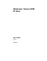
The following illustration shows the location of the LEDs on the diagnostic panel.
The diagnostic panel LEDs are visible through a special cutout area located to the left
of the cover-release latch on the top cover. However, to determine the exact location
of the error condition in your server, you might need to remove the top cover to view
the location of the error LED on the diagnostic panel.
Note:
The diagnostic panel is also called the LED card.
The meanings of these LEDs are as follows:
NMI
Nonmaskable
interrupt
SP Bus
Service
processor
failure
PCI Bus A (PCIA)
PCI bus A fault
PCI Bus B (PCIB)
PCI bus B fault
PCI Bus C (PCIC)
PCI bus C fault
DASD
Hard disk drive fault
Memory
Memory
fault
CPU
Microprocessor
fault
FAN
Fan
failure
TEMP
System temperature failure
NON RED
Nonredundant power mode
OVER SPEC
Over
specification
Power supply 1
Power supply number 1 failure
Power supply 2
Power supply number 2 failure
Power supply 3
Power supply number 3 failure
System board connector
Diskette drive connector
CPU
Memory
Fan
A B C
1 2 3
DASD
NMI
SP Bus
Event Log
Non Red
Over Spec
Temp
PCI
Bus
Power
Supply
Содержание eserver xSeries 350
Страница 1: ...User s Reference xSeries 350 ...
Страница 2: ......
Страница 3: ...IBM IBM xSeries 350 User s Reference SC21 P902 60 ...
Страница 12: ...x IBM xSeries 350 User s Reference ...
Страница 22: ...10 IBM xSeries 350 User s Reference ...
Страница 34: ...22 IBM xSeries 350 User s Reference ...
Страница 40: ...28 IBM xSeries 350 User s Reference ...
Страница 90: ...78 IBM xSeries 350 User s Reference ...
Страница 148: ...136 IBM xSeries 350 User s Reference ...
Страница 154: ...142 IBM xSeries 350 User s Reference ...
Страница 170: ...158 IBM xSeries 350 User s Reference ...
Страница 173: ......
Страница 174: ...IBM Part Number 21P9026 21P9 26 ...