


Power Supplies
DANGER
Do not attempt to open the covers of the power supply. Power supplies are not serviceable and
are to be replaced as a unit.
D02
This system drawer has power supplies that have hot-swap capabilities. To use this feature, you
must
have two power supplies in place.
Before performing any of the following procedures, read and understand all of the safety notices beginning
with “Safety Notices” on page xi.
Non-Hot-Swap Power Supply Removal
If you are servicing a system that has only one power supply installed, you must follow the non-hot-swap
power supply removal procedure. Systems that were configured with one power supply at the factory have
a power supply filler panel. The filler panel protects the vacant power supply connector from dust or
damage.
To remove a non-hot-swap power supply, do the following:
1. On a Model 6C4, open the front and rear rack doors and place the system into the service position as
described in “Placing the Model 6C4 into the Service Position” on page 429.
On a Model 6E4, open the bezel door.
2. Shut down the system as described in either “Stopping the System without an HMC Attached” on
page 424, “Stopping the System with an HMC Attached and AIX Installed” on page 424, or “Stopping
the System with an HMC Attached and Linux Installed” on page 425.
3. Remove the service access cover as described in “Service Access Cover Removal (Model 6C4)” on
page 431 or “Service Access Cover Removal (Model 6E4)” on page 436.
4. Remove the power cable from the rear of the power supply.
5. Wait at least 10 seconds before performing the next step.
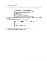
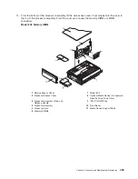
6. Grasp the ends of both power supply handles, and slide the retractable spring-activated portion of
each handle toward its hinged base. This action releases the locking tab located on the bottom side of
each release handle. See the following illustration.
1
Power Supply
2
Locking Tab Receiver Hole
3
Retractable Spring-Activated Portion of the Handle
7. Lift the handle until it is perpendicular (90 degrees) to the top of the power supply. By placing the
handle perpendicular to the top of the power supply, the base or hinged portion of each handle acts as
a cam and will gently pry the power supply from its connector located on the CEC backplane.
Chapter 9. Removal and Replacement Procedures
501
Содержание @Server pSeries 630 6C4
Страница 1: ...pSeries 630 Model 6C4 and Model 6E4 Service Guide SA38 0604 03 ERserver...
Страница 2: ......
Страница 3: ...pSeries 630 Model 6C4 and Model 6E4 Service Guide SA38 0604 03 ERserver...
Страница 16: ...xiv Eserver pSeries 630 Model 6C4 and Model 6E4 Service Guide...
Страница 18: ...xvi Eserver pSeries 630 Model 6C4 and Model 6E4 Service Guide...
Страница 382: ...362 Eserver pSeries 630 Model 6C4 and Model 6E4 Service Guide...
Страница 440: ...420 Eserver pSeries 630 Model 6C4 and Model 6E4 Service Guide...
Страница 535: ...Chapter 10 Parts Information This chapter contains parts information for the pSeries 630 Model 6C4 and Model 6E4 515...
Страница 538: ...System Parts continued 518 Eserver pSeries 630 Model 6C4 and Model 6E4 Service Guide...
Страница 541: ...Chapter 10 Parts Information 521...
Страница 562: ...542 Eserver pSeries 630 Model 6C4 and Model 6E4 Service Guide...
Страница 568: ...548 Eserver pSeries 630 Model 6C4 and Model 6E4 Service Guide...
Страница 576: ...556 Eserver pSeries 630 Model 6C4 and Model 6E4 Service Guide...
Страница 580: ...560 Eserver pSeries 630 Model 6C4 and Model 6E4 Service Guide...
Страница 616: ...596 Eserver pSeries 630 Model 6C4 and Model 6E4 Service Guide...
Страница 646: ...626 Eserver pSeries 630 Model 6C4 and Model 6E4 Service Guide...
Страница 649: ......
Страница 650: ...Printed in U S A May 2003 SA38 0604 03...


