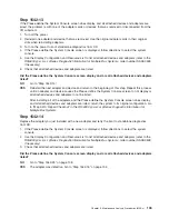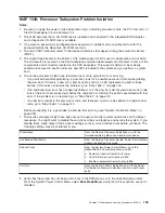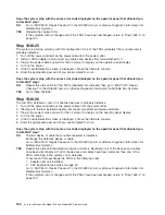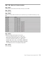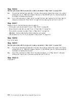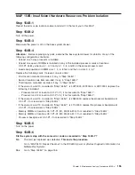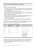
Step 1548-13
The system is working correctly with this configuration. The diskette drive may be defective.
1. Make sure the diagnostic CD-ROM is inserted into the CD-ROM drive.
2. Turn off the power and remove the power cords.
3. Plug the diskette drive cable into the diskette drive connector on the CEC backplane.
4. Connect the signal and power connectors to the diskette drive.
5. Plug in the power cords and wait for the
OK
prompt to display on the operator panel display.
6. Turn on the power.
7. After the word
keyboard
displays, press the number 5 key on either the directly attached keyboard or
on an ASCII terminal keyboard.
8. If you are prompted to do so, enter the appropriate password.
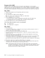
Is the Please define the System Console screen displayed?
NO
One of the FRUs remaining in the system is defective.
Exchange the FRUs that have not been exchanged, in the following order:
1. Diskette drive
2. Diskette drive cable
3. CEC backplane (see notes on page 61)
Repeat this step until the defective FRU is identified or all the FRUs have been exchanged.
If the symptom did not change and all the FRUs have been exchanged, call service support for
assistance.
If the symptom has changed, check for loose cards, cables, and obvious problems. If you do not
find a problem return, go to the “Quick Entry MAP” on page 63 and follow the instructions for the
new symptom.
YES
Go to “Step 1548-14”.
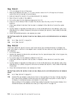
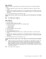
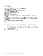
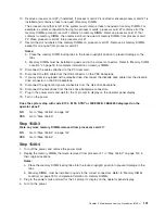
Step 1548-14
The system is working correctly with this configuration. One of the devices that you disconnected from the
CEC backplane may be defective.
1. Turn off the power and remove the power cords.
2. Attach a CEC backplane device (for example: parallel, serial port 1, serial port 2, serial port 3,
keyboard, mouse, Ethernet, Ultra-2 SCSI) that had been removed.
3. Plug in the power cords and wait for the
OK
prompt to display on the operator panel display.
4. Turn on the power.
5. If the Console Selection screen is displayed, choose the system console.
6. After the word
keyboard
displays, press the number 5 key on either the directly attached keyboard or
on an ASCII terminal keyboard.
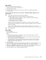
7. If you are prompted to do so, enter the appropriate password.
Chapter 3. Maintenance Analysis Procedures (MAPs)
147
Содержание @Server pSeries 630 6C4
Страница 1: ...pSeries 630 Model 6C4 and Model 6E4 Service Guide SA38 0604 03 ERserver...
Страница 2: ......
Страница 3: ...pSeries 630 Model 6C4 and Model 6E4 Service Guide SA38 0604 03 ERserver...
Страница 16: ...xiv Eserver pSeries 630 Model 6C4 and Model 6E4 Service Guide...
Страница 18: ...xvi Eserver pSeries 630 Model 6C4 and Model 6E4 Service Guide...
Страница 382: ...362 Eserver pSeries 630 Model 6C4 and Model 6E4 Service Guide...
Страница 440: ...420 Eserver pSeries 630 Model 6C4 and Model 6E4 Service Guide...
Страница 535: ...Chapter 10 Parts Information This chapter contains parts information for the pSeries 630 Model 6C4 and Model 6E4 515...
Страница 538: ...System Parts continued 518 Eserver pSeries 630 Model 6C4 and Model 6E4 Service Guide...
Страница 541: ...Chapter 10 Parts Information 521...
Страница 562: ...542 Eserver pSeries 630 Model 6C4 and Model 6E4 Service Guide...
Страница 568: ...548 Eserver pSeries 630 Model 6C4 and Model 6E4 Service Guide...
Страница 576: ...556 Eserver pSeries 630 Model 6C4 and Model 6E4 Service Guide...
Страница 580: ...560 Eserver pSeries 630 Model 6C4 and Model 6E4 Service Guide...
Страница 616: ...596 Eserver pSeries 630 Model 6C4 and Model 6E4 Service Guide...
Страница 646: ...626 Eserver pSeries 630 Model 6C4 and Model 6E4 Service Guide...
Страница 649: ......
Страница 650: ...Printed in U S A May 2003 SA38 0604 03...

