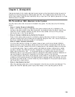
IPL Flow without an HMC Attached to the System
The IPL process starts when ac power is connected to the system. The IPL process has the following
phases:
v
Phase 1: Service Processor Initialization
Phase 1 starts when ac power is connected to the system and ends when OK is displayed in the media
subsystem operator panel. 8xxx checkpoints are displayed during this phase. Several 9xxx codes may
also be displayed. Service processor menus are available at the end of this phase by striking any key
on the console keyboard.
v
Phase 2: Hardware Initialization by the Service Processor
Phase 2 starts when system power-on is initiated by pressing the power on button on the processor
subsystem operator panel. 9xxx checkpoints are displayed during this time. 91FF, the last checkpoint in
this phase, indicates the transition to phase 3 is taking place.
v
Phase 3: System Firmware initialization
At phase 3, a system processor takes over control and continues initializing partition resources. During
this phase, checkpoints in the form Exxx are displayed. E105, the last checkpoint in this phase,
indicates that control is being passed to the operating system boot program.
v
Phase 4: Operating System Boot
When the operating system starts to boot, checkpoints in the form 0xxx and 2xxx are displayed. This
phase ends when the operating system login prompt displays on the operating system console.
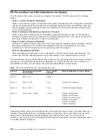
The following table outlines the IPL phases from power-on to the operating system login prompt, matching
the phases to corresponding operator-panel checkpoints for a typical partition boot. Also listed are the
approximate boot times for each phase, along with their dependencies for each phase.
Note:
The following table lists the major checkpoints only.
Phase #
Checkpoints on Operator
Panel or HMC
Time in Phase
(minutes)
Major Contributors to Time in Phase
Phase 1
8xxx => OK
Approx. 1
Phase 2
9xxx => 91FF
3 to 6
Number of I/O drawers
Phase 3
Exxx => E105
1 to 3
Number of bootable adapters
Phase 4
0xxx or 2xxx => blank
2 to 30+
Number of SSA drives
Number of SCSI drives
Number of Async sessions
Number of processors
Number of adapters
Amount of memory
Checkpoints enable users and service personnel to know what the server is doing, with some detail, as it
initializes. These checkpoints are not intended to be error indicators, but in some cases a server could
hang at one of the checkpoints without displaying an 8-character error code. It is for these hang
conditions, only, that any action should be taken with respect to checkpoints. The most appropriate action
is included with each checkpoint.
160
Eserver
pSeries 630 Model 6C4 and Model 6E4 Service Guide
Содержание @Server pSeries 630 6C4
Страница 1: ...pSeries 630 Model 6C4 and Model 6E4 Service Guide SA38 0604 03 ERserver...
Страница 2: ......
Страница 3: ...pSeries 630 Model 6C4 and Model 6E4 Service Guide SA38 0604 03 ERserver...
Страница 16: ...xiv Eserver pSeries 630 Model 6C4 and Model 6E4 Service Guide...
Страница 18: ...xvi Eserver pSeries 630 Model 6C4 and Model 6E4 Service Guide...
Страница 382: ...362 Eserver pSeries 630 Model 6C4 and Model 6E4 Service Guide...
Страница 440: ...420 Eserver pSeries 630 Model 6C4 and Model 6E4 Service Guide...
Страница 535: ...Chapter 10 Parts Information This chapter contains parts information for the pSeries 630 Model 6C4 and Model 6E4 515...
Страница 538: ...System Parts continued 518 Eserver pSeries 630 Model 6C4 and Model 6E4 Service Guide...
Страница 541: ...Chapter 10 Parts Information 521...
Страница 562: ...542 Eserver pSeries 630 Model 6C4 and Model 6E4 Service Guide...
Страница 568: ...548 Eserver pSeries 630 Model 6C4 and Model 6E4 Service Guide...
Страница 576: ...556 Eserver pSeries 630 Model 6C4 and Model 6E4 Service Guide...
Страница 580: ...560 Eserver pSeries 630 Model 6C4 and Model 6E4 Service Guide...
Страница 616: ...596 Eserver pSeries 630 Model 6C4 and Model 6E4 Service Guide...
Страница 646: ...626 Eserver pSeries 630 Model 6C4 and Model 6E4 Service Guide...
Страница 649: ......
Страница 650: ...Printed in U S A May 2003 SA38 0604 03...

