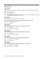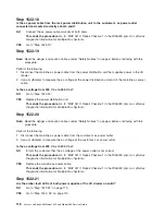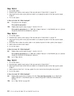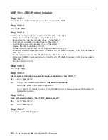
Step 1522-22
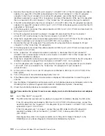
Replace the items in the following list one at a time. Turn off the power before removing the item, and turn
the power back on after replacing the item to determine if the drawer will power on.
1. Replace the power supply with the amber fault LED on solid.
2. Replace the other power supply with the one just removed.
3. Replace the I/O drawer backplane.
Does the I/O drawer power on?
NO
Have all the items in the list above been replaced?
NO
Go to “Step 1522-22” and replace the next item.
YES
Call service support.
YES
The item just replaced was defective.
This ends the procedure.
Go to
″
MAP 0410: Repair
Checkout
″
in the
RS/6000
Eserver
pSeries Diagnostic Information for Multiple Bus Systems
.
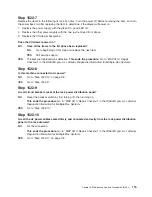
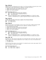
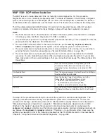
Step 1522-23
Are the amber fault LEDs of both power supplies of the I/O drawer blinking?
NO
Go to “Step 1522-24”.
YES
Go to “Step 1522- 25”.
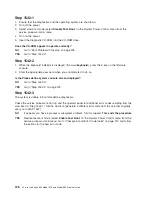
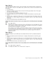
Step 1522-24
Perform the action items in the following list one at a time. Turn the power off before removing the item,
and turn the power back on after replacing the item to determine if the drawer will power on.
1. Check all SPCN external cabling.
2. Replace the power supply with the amber fault LED blinking.
3. Replace the other power supply with the one just removed.
4. Replace the I/O drawer backplane.
Does the I/O drawer power on?
NO
Have all the items in the list above been replaced?
NO
Go to “Step 1522-24”, and replace the next item.
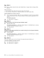
YES
Call service support.
YES
The item just replaced was defective.
This ends the procedure.
Go to
″
MAP 0410: Repair
Checkout
″
in the
RS/6000
Eserver
pSeries Diagnostic Information for Multiple Bus Systems
.
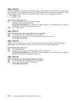
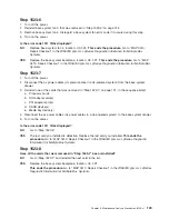
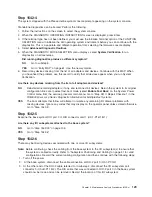
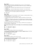
Step 1522- 25
Disconnect the ac power cable (dc power cable for a dc-powered system) to each power supply of the I/O
drawer and remove the following components from the I/O drawer, one at a time, in the sequence listed:
1. RIO adapter card
2. PCI adapter card(s)
Reconnect the ac power cables (dc power cable for a dc-powered system) to each power supply of the I/O
drawer and attempt to power on the I/O drawer.
Does the I/O drawer power-on?
NO
Go to “Step 1522-28” on page 120.
YES
Go to “Step 1522-26” on page 120.
Chapter 3. Maintenance Analysis Procedures (MAPs)
119
Содержание @Server pSeries 630 6C4
Страница 1: ...pSeries 630 Model 6C4 and Model 6E4 Service Guide SA38 0604 03 ERserver...
Страница 2: ......
Страница 3: ...pSeries 630 Model 6C4 and Model 6E4 Service Guide SA38 0604 03 ERserver...
Страница 16: ...xiv Eserver pSeries 630 Model 6C4 and Model 6E4 Service Guide...
Страница 18: ...xvi Eserver pSeries 630 Model 6C4 and Model 6E4 Service Guide...
Страница 382: ...362 Eserver pSeries 630 Model 6C4 and Model 6E4 Service Guide...
Страница 440: ...420 Eserver pSeries 630 Model 6C4 and Model 6E4 Service Guide...
Страница 535: ...Chapter 10 Parts Information This chapter contains parts information for the pSeries 630 Model 6C4 and Model 6E4 515...
Страница 538: ...System Parts continued 518 Eserver pSeries 630 Model 6C4 and Model 6E4 Service Guide...
Страница 541: ...Chapter 10 Parts Information 521...
Страница 562: ...542 Eserver pSeries 630 Model 6C4 and Model 6E4 Service Guide...
Страница 568: ...548 Eserver pSeries 630 Model 6C4 and Model 6E4 Service Guide...
Страница 576: ...556 Eserver pSeries 630 Model 6C4 and Model 6E4 Service Guide...
Страница 580: ...560 Eserver pSeries 630 Model 6C4 and Model 6E4 Service Guide...
Страница 616: ...596 Eserver pSeries 630 Model 6C4 and Model 6E4 Service Guide...
Страница 646: ...626 Eserver pSeries 630 Model 6C4 and Model 6E4 Service Guide...
Страница 649: ......
Страница 650: ...Printed in U S A May 2003 SA38 0604 03...


