8-12
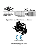
MAST LOAD ROLLER AND BACK UP
LINER
2 stage mast(V mast)
Remove the carriage assembly and
move them to one side.
Loosen and remove hexagon bolts and
nuts securing lift cylinders to outer mast.
Loosen and remove hexagon nuts and
set screw securing lift cylinders to inner
mast.
Attach chains or sling to the inner mast
section at top crossmember. Using an
overhead hoist, slowly raise the inner
mast high enough to clear lift cylinder.
After lowering the lift cylinder rods, and
disconnecting lift cylinder hose, tilt the lift
cylinders LH and RH and them with
ropes to the outer mast.
Using the overhead hoist, lower inner
mast until top and bottom rollers and
back up liners are exposed.
Using a pryer, remove load rollers from
load roller bracket. Remove back up
liners and shims.
Thoroughly clean, inspect and replace all
worn or damaged parts.
Reverse the above procedure to
assemble. Refer to MAST LOAD
ROLLER ADJUSTMENT paragraph.
4)
(1)
①
②
③
④
⑤
⑥
⑦
⑧
⑨
Lift
cylinder
Set screw
Chain
Hexagon nut
Inner
mast
Mast load
roller
Hexagon
bolt
Hexagon
nut
Side
roller
Mast load
roller
Outer
mast
60L7AMS16
Содержание 60L-7A
Страница 11: ...SECTION 1 GENERAL Group 1 Safety hints 1 1 Group 2 Specifications 1 5 Group 3 Periodic replacement 1 13 ...
Страница 25: ...SECTION 2 REMOVAL INSTALLATION OF UNIT Group 1 Structure 2 1 Group 2 Removal and installation of unit 2 2 ...
Страница 32: ...2 7 Mast Refer to section on mast Page 2 2 1 2 POWER TRAIN ASSEMBLY REMOVAL 1 D503RE04 ...
Страница 69: ...3 28 50DFTM13 Remove bearing 67 and gear 68 30 68 67 ...
Страница 71: ...3 30 Remove oil seal 72 from the transmission case 34 50DFTM17 72 ...
Страница 98: ...3 57 Assemble wheel hub and tighten plug 14 Tightening torque 35 60kgf m 253 2 434 0lbf ft 12 50D7EDA61 ...
Страница 147: ...5 31 2 PRIORITY VALVE STRUCTURE 50DS7ESE08 1 Body 2 Spool 3 Spring plug 4 End plug 5 Spring 6 O ring 7 Orifice 1 ...
Страница 188: ...7 3 10MM RING ELECTRIC CIRCUIT FOR LPG FUE KIT 35L7AEL07 ...
Страница 189: ...7 4 MEMORANDUM ...