background image

ENGINE  3-28

Oversize oil ring

The following two types of oversize oil ring are used.
They bear the following identification marks.

Color classification

Painted red

Painted yellow

Oversize oil ring

0.5 mm

1.0 mm

2nd

05

10

1st

05

10

Oversize piston ring

0.5 mm

1.0 mm

OVERSIZE RINGS

Oversize piston ring

The following two types of oversize piston ring are used.
They bear the following identification numbers.

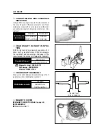
CONROD SMALL END INSIDE DIAM-
ETER INSPECTION

Using a dial calipers, measure the conrod small end 
inside diameter both in vertical and horizontal directions. 
If any of the measurements exceeds the service
limit, replace the conrod.

Standard

20.006~20.014 mm

(0.7876~0.7880 in)

Service limit

20.040 mm

(0.7890 in)

Conrod small

end I.D.

CONROD DEFLECTION INSPECTION

Move the small end sideways while holding the big end 
immovable in thrust direction.
Measure the amount of deflection.
Turn the conrod and see if it moves smoothly without 
play and noise. This method can check the extent of
wear on the parts of the conrod

s big end.

Conrod deflection

Service limit

3.0mm (0.12 in)

Dial calipers : 09900-20605

Dial gauge : 09900-20606
Magnetic stand : 09900-20701
V-block : 09900-21304

Содержание GT 650

Страница 1: ...GT 650 Fra 2004 og frem Servicemanual Holtvej 8 10 Høruphav 6470 Sydals Telefon 45 73 15 11 00 Fax 45 73 15 11 01 E mail info scanmi dk www scanmi dk CVR 27 73 31 07 ...

Страница 2: ...INERY INC FOREWORD This manual contains an introductory description on HYOSUNG and procedures for its inspection service and overhaul of its main components Other information considered as generally known is not included Read GENERAL INFORMATION section to familiarize yourself with outline of the vehicle and MAINTENANCE and other sections to use as a guide for proper inspec tion and service This m...

Страница 3: ... sections are listed on the previous page as GROUP INDEX select the section where you are look ing for 3 Holding the manual as shown at the right will allow you to find the first page of the section easily 4 On the first page of each section its contents are listed Find the item and page you need COMPONENT PARTS Example Front wheel ...

Страница 4: ...or use brake fluid Measure in voltage range Measure in resistance range Measure in current range Use special tool Use engine coolant Torque control required Data beside it indicates specified torque Apply oil Use engine oil unless otherwise specified Apply SUPER GREASE A Apply SILICONE GREASE Apply MOLY PASTE Apply BOND 1215 Use fork oil DEFINITION SYMBOL DEFINITION SYMBOL Apply SUPER GREASE C ...

Страница 5: ...NOTE Difference between photographs and actual motorcycles depends on the markets ...

Страница 6: ...RMATION LABELS 1 1 GENERAL PRECAUTIONS 1 1 SERIAL NUMBER LOCATION 1 3 FUEL OIL AND ENGINE COOLANT RECOMMENDATIONS 1 4 BREAK IN PROCEDURES 1 6 CYLINDER CLASSIFICATION 1 6 EXTERIOR ILLUSTRATION 1 7 SPECIFICATIONS 1 8 CONTENTS 1 ...

Страница 7: ...t could result in vehicle damage WARNING Indicates a potential hazard that could result in death or injury NOTE Indicates special information to make maintenance easier or instructions cleaner WARNING Proper service and repair procedures are important for the safety of the service machanic and the safe ty and reliability of the vehicle When 2 or more persons work together pay attention to the safe...

Страница 8: ...er head and case bolts and nuts beginning with larger diameter and ending with small er diameter from inside to outside diagonally to the specified tightening torque Whenever you remove oil seals gaskets packing O rings locking washers cotter pins circlips and certain other parts as specified be sure to replace them with new ones Also before installing these new parts be sure to remove any left ov...

Страница 9: ...on Number is stamped on the steering head tube The engine seri al number is located on the left down of crankcase assembly These numbers are required especially for registering the machine and ordering spare parts FRAME SERIAL NUMBER ENGINE SERIAL NUMBER 1 3 GENERAL INFORMATION ...

Страница 10: ...GINE OIL SPECIFICATION WARNING Don t mix the unrecommended oil It could damage the engine When refilling the oil tank don t allow the dust to get inside Mop the oil spilt Don t put the patch on the cap It could disturb the oil to be provided and damage the engine WARNING Since the brake system of this motorcycle is filled with a glycol based brake fluid by the manufacturer do not use or mix differ...

Страница 11: ...erature in your area does not go down to freezing point Hyosung recommends the use of HYOSUNG COOLANT anti freeze engine coolant If this is not available use an equivalent which is compatible with an aluminum radiator LIQUID AMOUNT OF WATER ENGINE COOLANT For engine coolant mixture information refer to cooling system section page 5 1 CAUTION Mixing of anti freeze engine coolant should be limited t...

Страница 12: ...le position BREAK IN PROCEDURES During manufacture only the best possible materials are used and all machined parts are finished to a very high standard but it is still necessary to allow the moving parts to BREAK IN before subjecting the engine to maximum stresses The future performance and reliability of the engine depends on the care and restraint exercised during its early life The general rul...

Страница 13: ...1 7 GENERAL INFORMATION EXTERIOR ILLUSTRATION ...

Страница 14: ...2 0 mm 2 44 in 647 39 5 in3 BDSR39 TYPE DOUBLE Electric starter Wet sump Type Number of cylinder Bore Stroke Piston displacement Carburetor Starter system Lubrication system Wet multi plate type 6 speed constant mesh 1 down 5 up 2 93 2 46 1 60 1 32 1 13 0 96 0 85 RK525XSO 108 links Clutch Transmission Gearshift pattern Final reduction Gear ratio 1st 2nd 3rd 4th 5th 6th Drive chain GENERAL INFORMAT...

Страница 15: ...lamp 15 A HI 60 W LO 55 W 10 W 21 5 W 1 7 W 3 1 7 W 1 7 W 2 5 W 1 7 W 1 2 1 7W E 1 7W Ignition type Ignition timing Spark plug Battery Turn signal lamp Brake Tail lamp Illumination lamp High beam indicator lamp Turn signal indicator lamp right left License plate lamp Neutral indicator lamp Fuel indicator lamp Fuel tank Engine oil oil change with filter change overhaul Front fork oil capacity One s...

Страница 16: ...S AND MUFFLER MOUNTING BOLTS 2 6 AIR CLEANER 2 7 CARBURETOR 2 7 FUEL HOSE 2 8 CLUTCH 2 9 ENGINE OIL 2 9 ENGINE OIL FILTER 2 11 DRIVE CHAIN 2 12 BRAKE SYSTEM 2 14 STEERING 2 18 FRONT FORK 2 18 REAR SUSPENSION 2 18 TIRE 2 19 CHASSIS BOLTS AND NUTS 2 19 ENGINE COOLANT 2 20 RADIATOR HOSE 2 22 COMPRESSION PRESSURE 2 23 OIL PRESSURE 2 24 CONTENTS 2 2 PERIODIC MAINTENANCE ...

Страница 17: ... Chassis bolts and nuts Inspect Inspect Inspect Inspect Inspect Tighten Inspect Inspect Inspect Inspect Inspect Inspect Inspect Tighten Clean and lubricate every 1 000km Replace every 4 years Replace every 2 years CHASSIS 2 12 2 14 2 14 2 14 2 19 2 18 2 18 2 18 2 19 PERIODIC MAINTENANCE SCHEDULE The chart below lists the recommended intervals for all the required periodic service work necessary to...

Страница 18: ...ts pivot Passenger footrests pivot Drive chain Side stand pivot and spring hook Speedometer gear box Front brake lever holder Throttle cable Rear brake pedal pivot O Motor oil G Grease NOTE Before lubricating each part clean off any rusty spots and wipe off any grease oil dirt or grime Lubricate exposed parts which are subject to rust with either motor oil or grease whenever the motor cycle has be...

Страница 19: ...r Refer to page 5 2 Remove the cylinder head cover bolt and Remove the magneto cover plug and the tim ing inspection plug 0 1 0 2 mm 0 004 0 008 in 0 2 0 3 mm 0 008 0 012 in IN EX Standard When cold Valve clearance Thickness gauge 09900 20806 Rotate the magneto rotor counter clockwise to set the front cylinder s piston at TDC Top Dead Center of the compression stroke Rotate the rotor until F line ...

Страница 20: ...shim selection chart please follow instruc tions of example in the below For example the intake clearance is 0 4 and the shim is 170 1 70 mm select 195 1 95 mm of the shim which 170 1 70 mm of the shim add up the excess clearance 0 25 mm when adjust with the standard 0 15 as the intake standard clearance 0 1 0 2 mm B D A C CAUTION Valve clearance should be checked when the engine is cold If you do...

Страница 21: ...ess gauge 09900 20806 SPARK PLUG Remove the three radiator mounting bolts Inspect Interval Clean Initial 1 000 km and Every 6 000 km Replace Every 12 000 km 2 5 PERIODIC MAINTENANCE Disconnect the spark plug caps Remove the spark plugs CAUTION Be careful not to damage the radiator fins Do not extract the radiator hose Remove the fuel tank WARNING The hot radiator and the hot engine can burn you Wa...

Страница 22: ... thread etc Install the spark plug and then tighten it to speci fied torque Spark plug 11 N m 1 1 kg m EXHAUST PIPE NUTS AND MUF FLER MOUNTING BOLTS Tighten the exhaust pipe nuts and muffler mount ing bolts to the specified torque Exhaust pipe nut 18 28 N m 1 8 2 8 kg m Muffler mounting bolt 18 28 N m 1 8 2 8 kg m Inspect Interval Tighten Initial 1 000 km and Every 6 000 km Rear Cylinder PERIODIC ...

Страница 23: ...ore frequent servicing may be performed on mo torcycles that are used under severe condi tions also clean the air cleaner element when replacing the oil to prevent damage of the engine CARBURETOR IDLE SPEED Inspect Interval Inspect Initial 1 000 km and Every 6 000 km 2 7 PERIODIC MAINTENANCE AIR CLEANER Remove the front and rear seat The air cleaner is located under the fuel tank Remove the fuel t...

Страница 24: ...lly closed posi tion slowly turn out the adjuster of the returning cable until resistance is felt Tighten the lock nut while holding the adjuster FUEL HOSE Remove the front and rear seat Refer to page 7 1 Remove the fuel tank Inspect the fuel hoses for damage and fuel leakage If any defects are found the fuel hoses must be replaced 1 300 1 500 rpm Engine idle speed 0 5 1 0 mm 0 02 0 04 in Throttle...

Страница 25: ...djuster lock nut Turn the clutch cable adjuster in or out to acquire the specified play After end of adjustment tighten the lock nut The clutch cable should be lubricated with a light weight oil whenever it is adjusted Necessary amount of engine oil Oil change Filter change Overhaul engine Engine oil type SAE 10W 40 API Over SG 3 000 3 200 3 400 GEARSHIFT LEVER HEIGHT ADJUSTMENT Loosen the lock nu...

Страница 26: ...in dow If the level is below mark L add oil to F level If the level is above mark F drain oil to F level Oil drain plug 21 N m 2 1 kg m CAUTION Never operate the motorcycle if the engine oil level is below the Lower line mark L in the inspec tion window Never fill the engine oil above the Upper line mark F Engine oil level being most suitable about 1mm under the Upper line mark F of the engine oil...

Страница 27: ...plug and exhaust pipes are cool enough to touch with bare hands before drain ing oil 2 11 PERIODIC MAINTENANCE ENGINE OIL FILTER Drain the engine oil as described in the engine oil replacement procedure Remove the oil filter cap Remove the oil filter Install the new O ring Install the new oil filter Install the new O ring and spring to the oil filter cap Install the oil filter cap Inspect Interval...

Страница 28: ... be replaced INSPECTION OF DRIVE CHAIN LENGTH Loosen the axle nut Loosen the lock nuts Tense the drive chain fully by turning both chain adjusters Add new engine oil and check the oil level as described in the engine oil replacement procedure CAUTION Use HYOSUNG MOTORS GENUINE OIL FILTER only since the other make s genuine filters and after market parts may differ filtering perfor mance and durabi...

Страница 29: ... mea sure the distance between the two points If the dis tance exceeds the service limit the chain must be replaced Service limit Drive chain 20pitch length 319 4 mm 12 58 in ADJUSTMENT OF DRIVE CHAIN SLACK Loosen the axle nut Loosen the lock nuts Loosen or tighten both chain adjusters until the chain has 20 30 mm of slack in the middle between the engine and rear sprockets The marks on both chain...

Страница 30: ...um product and will provide some lubrication as well as cleaning action After washing and drying the chain oil it with a engine oil or chain lubricating oil CAUTION The drive chain for this motorcycle is made of the special material The chain should be replaced with a RK525XSO for Use of another chain may lead to premature chain failure Inspect Interval BRAKE Inspect Initial 1 000 km and Every 6 0...

Страница 31: ...caliper mounting bolt 18 28 N m 1 8 2 8 kg m CAUTION Replace the brake pad as a set otherwise braking performance will be adversely affected WARNING The brake system of this motorcycle is filled with a glycol based brake fluid Do not use or mix dif ferent types of fluid such as silicone based or petroleum based Do not use any brake fluid taken from old used or unsealed containers Never re use brak...

Страница 32: ...the hose into a receptacle Specification and Classification Front brake DOT 4 Rear brake DOT 4 Close the air bleeder valve and disconnect the clear hose Fill the reservoir with new brake fluid to the upper line Replace the rear brake s fluid with the same man ner of the front brake Front brake caliper air bleeder valve 6 8 N m 0 6 0 8 kg m Rear brake caliper air bleeder valve 6 8 N m 0 6 0 8 kg m ...

Страница 33: ...the brake system Squeeze and release the brake lever several times in rapid succession and sqeeze the lever fully with out releasing it Loosen the bleeder valve by turn ing it a quarter of a turn so that the brake fluid runs into the receptacle this will remove the tension of the brake lever causing it to touch the handlebar grip Then close the air bleeder valve pump and squeeze the brake lever an...

Страница 34: ...rface of the inner tubes Replace any defective parts if necessary REAR SUSPENSION Inspect the rear shock absorber for oil leakage and mounting rubbers including engine mounting for wear and damage Replace any defective parts if neces sary Refer to page 7 32 Inspect Interval Inspect Initial 1 000 km and Every 6 000 km Inspect Interval Inspect Every 6 000 km Inspect Interval Inspect Every 6 000 km P...

Страница 35: ...to their specified torque Refer to page 8 13 COLD INFLATION TIRE PRESSURE Front Rear SOLO RIDING KPa 221 245 2 25 2 50 33 0 36 0 221 245 2 25 2 50 33 0 36 0 kgf cm2 psi DUAL RIDING KPa kgf cm2 psi TIRE PRESSURE If the tire pressure is too high or too low steering will be adversely affected and tire wear increased Therefore maintain the correct tire pressure for good roadability or shorter tire lif...

Страница 36: ...wallowed of if it comes in contact with skin of eyes Keep out of the reach of children and animals CAUTION Use distilled water only Water other than distilled water can corrode and clog the aluminum radia tor The 50 50 mixture of distilled water and ethylene glycol anti freeze will provide the optimum corro sion protection and excellent heat protection and will protect the cooling system from free...

Страница 37: ...dd engine coolant up to the raditor cap inlet Support the motorcycle upright Slowly swing the motorcycle right and left to bleed the air trapped in the cooling circuit Add engine coolant up to the radiator cap inlet Start up the engine and bleed air from the radiator cap inlet completely Add engine coolant up to the radiator cap inlet Repeat the above procedure until no air bleed from the radiator...

Страница 38: ...DIATOR HOSE Check to see the radiator hose for crack damage or engine coolant leakage If any defects are found replace the radiator hoses with new ones Inspect Interval Inspect Every 6 000km Replace the radiator hose Every 4 years ...

Страница 39: ...l compression pressure readings are nearly 12kg even when they measure more than 12kg COMPRESSION TEST PROCEDURE Compression gauge 09915 64510 COMPRESSION PRESSURE The compression of a cylinder is a good indicator of its internal condition The decision to overhaul the cylinder is often based on the results of a compression test Periodic mainte nance records kept at your dealership should include c...

Страница 40: ... rpm After warming up increase the engine speed to 3 000 rpm with the engine tachometer and read the oil pressure gauge Oil pressure gauge 09915 74510 Engine tachometer 09900 26006 LOW OIL PRESSURE Oil leakage from the oil passage Damaged O ring Defective oil pump Combination of above items OIL PRESSURE Check the oil pressure periodically This will give a good indication of the condition of the mo...

Страница 41: ...n identification of assembly location on each removed part so that each will be restored to the original position during reassembly Wash clean and dry the removed parts before inspecting and measuring Oil the rotating or sliding parts before assembly Make sure to use the correct type of lubricant where specified Check that each rotating or sliding part moves or operates smoothly after assembly Mak...

Страница 42: ...ENGINE REMOVAL Remove the front seat Refer to page 7 1 Remove the fuel tank Refer to page 4 1 Disconnect the battery lead wire NOTE If the engine is dirtied wash the machine with a suitable cleaner before removing the engine CAUTION First disconnect the lead wire Drain engine oil Refer to page 2 10 Drain engine coolant Refer to page 2 20 ...

Страница 43: ...ler Disconnect the radiator outlet hose Disconnect the reserve tank hose Remove the radiator mounting bolts Refer to page 5 2 Disconnect the radiator inlet hose Disconnect the cooling fan motor lead wire coupler Remove the radiator CAUTION Be careful not to bend the radiator fin ...

Страница 44: ... lever Disconnect the clutch cable end out of clutch release arm EXHAUST PIPE AND MUFFLER With the exhaust pipe bolts and muffler mounting bolts removed remove the exhaust pipes and muf fler CARBURETOR Remove the carburetor after removed the intake pipes Refer to page 4 4 Disconnect the vacuum hoses ...

Страница 45: ...ront Cylinder Rear Cylinder ELECTRIC PARTS With take out the spark plug caps remove the spark plug Remove the starter motor lead wire Disconnect the engine coolant temperature sensor lead wire ENGINE 3 4 ...

Страница 46: ...t the two magneto coupler Disconnect the neutral switch terminal Disconnect the side stand switch lead wire couper ENGINE SPROCKET Remove the engine sprocket cover Disconnect the front side of crankcase breather hose and rear side of crankcase breather hose ...

Страница 47: ...the carburetor when removing or installing the engine necessarily When removing the carburetor loosen the intake pipe mounting bolts at the same time Remove the gearshift arm Flatten the lock washer Remove the engine sprocket nut and washer Remove the engine sprocket NOTE When loosening the engine sprocket nut depress the brake pedal NOTE If it is difficult to remove the engine sprocket loosen the...

Страница 48: ... 5 3 0 kg m Engine mounting nut 45 70 N m 4 5 7 0 kg m Engine mounting lock nut M26 70 80 N m 7 0 8 0 kg m Engine mounting lock nut M20 35 50 N m 3 5 5 0 kg m CAUTION Set the part of engine mounting bolt align center line by the hand temporarily and install the engine mounting bolt to the specified torque If otherwise it is damage to the thread of engine mounting bolt NOTE Set the part of swingarm...

Страница 49: ...er to page 2 9 Install the breather hose and engine sprocket cover Connect each electric parts and its couplers Refer to page 8 24 28 Install the exhaust pipes and mufflers Install the carburetor and air cleaner Refer to page 4 7 Install the radiator Refer to page 5 4 After remounting the engine the following adjustments are necessary Engine idling speed Refer to page 2 7 Throttle cable play Refer...

Страница 50: ...emove the contacts and springs THERMOSTAT Remove the thermostat case along with the hose CAUTION Identify the position of each removed part Organize the parts in their respective groups so that they can be reinstalled in their original positions NOTE Thermostat inspection and servicing Refer to page 5 8 ...

Страница 51: ...er head cover 2ND AIR VALVE Remove the 2nd air valve with the bracket CAUTION Align the index mark on the magneto rotor with the index mark on the magneto cover as turn the crankshaft counter clockwise To set piston at TDC Top Dead Center of the compression stroke as align the F mark for front cylinder and the R mark for rear cylin der ...

Страница 52: ...bolts removed remove the cam chain guide NO 2 Remove the camshaft housing Remove the camshaft IN EX NOTE Mark an identification of assembly location on each removed parts so that each will be restored to the original position during reassembly ...

Страница 53: ... shim with the strong magnet not to be scratched ENGINE 3 12 Loosen the six cylinder head bolts Remove the chain guide NO 1 and cylinder head Loosen the cylinder head base bolt NOTE When loosening the cylinder head bolts loosen each bolt little by little diagonally ...

Страница 54: ... the valve cotter from the valve stem Remove the valve spring retainer Pull out valve from the other side CAUTION The tappet and shim should be lined so that each will be restored to the original position during reassembly Remove the two cylinder base nuts and cylinder CAUTION If tapping with the plastic hammer is necessary pay attention to break the fins ...

Страница 55: ...kcase Remove the piston pin circlips with long nose pliers Piston pin puller 09910 34510 Remove the piston pin by using the special tool Remove the rear cylinder head and cylinder with the same manner of the front cylinder head and cylinder removal NOTE Make an identification on each piston head so that confirmed the cylinder Rear Cylinder Front Cylinder ...

Страница 56: ...nrod holder 09910 20115 Rotor remover 09930 30165 MAGNETO ROTOR With the magneto rotor held immovable using the special tool loosen the rotor nut Remove the magneto rotor by using the special tool Remove the key Remove the starter driven gear Remove the cam chain ...

Страница 57: ...COVER Remove the clutch release arm Remove the clutch cover bolts Remove the clutch cover Remove the cam chain tensioner NOTE When remove or inspect the clutch drive and driven plate remove only the clutch pressure cover ...

Страница 58: ...nrod holder 09910 20115 Remove the disk pressure Remove the clutch drive plates NO 1 and driven plates Remove the spring washer and spring washer seat Remove the clutch drive plate NO 2 Flatten the lock washer Clutch sleeve hub holder 09920 53710 With the clutch sleeve hub held immovable using special tool remove the clutch sleeve hub nut ...

Страница 59: ...ly Conrod holder 09910 20115 PRIMARY DRIVE GEAR With the crankshaft held immovable using special tool remove the primary drive gear nut Remove the water pump drive gear and primary drive gear CAUTION This nut has left hand thread If turning it counter clockwise it may cause damage Pay attention at the primary drive gear nut with a washer and water pump drive gear with a washer ...

Страница 60: ...oil pump GEARSHIFT SHAFT Draw out the gearshift shaft Remove the gearshift cam stopper Loosen the gearshift cam plate bolt Remove the gearshift cam stopper plate Remove the crankcase securing bolts right and left NOTE Loosen the crankcase bolts diagonally and smaller sizes first ...

Страница 61: ...ecial tool Crankcase separator 09920 13120 CAUTION When separating the crankcase necessarily remove it after installed the special tool Crankcase separator on the side of clutch In case separate oppositely the gearshift cam stopper will be damaged in the side of magneto NOTE Fit the crankcase separater so that the tool arms parallel the side of the crankcase Remove the mission oil pipe mounting bo...

Страница 62: ...E STEM RUNOUT Check the valve stem for abnormal wear or bend Place the valve on V blocks and measure runout If the service limit is exceeded or abnormal condi tion exists replace the valve Dial gauge 09900 20606 Magnetic stand 09900 20701 V block 09900 21304 CYLINDER HEAD DISTORTION Decarbonate in combustion chamber Check the gasketed surface of the cylinder head for dis tortion with a straighteda...

Страница 63: ...f these abnormality could be caused by a worn camshaft CAMSHAFT WEAR Worn down cams are often the cause of mistimed valve operation resulting in reduced output power The limit of cam wear is specified for both intake and exhaust cams in terms of cam height which is to be measured with a micrometer Replace camshafts if found it worn down to the limit CAMSHAFT JOURNAL WEAR Determine whether or not e...

Страница 64: ...ameter Standard 4 465 4 480 mm 0 1758 0 1764 in 4 455 4 470 mm 0 1754 0 1760 in IN EX VALVE HEAD RADIAL RUNOUT Place a dial gauge as shown and measure valve head radial runout If the service limit is exceeded replace the valve Dial gauge 09900 20606 Magnetic stand 09900 20701 V block 09900 21304 Dial gauge 09900 20606 Magnetic stand 09900 20701 Micrometer 0 25 mm 09900 20201 VALVE STEM DIAMETER Me...

Страница 65: ...ion Inner Outer Standard 4 2 4 8 kgf 9 3 10 6 lbs at length 29 9 mm 1 18 in 17 0 19 6 kgf 37 5 43 2 lbs at length 33 4 mm 1 32 in Standard 81 500 81 515 mm 3 2087 3 2093 in Service limit 81 575 mm 3 2116 in Cylinder bore Cylinder distortion Service limit 0 05 mm 0 002 in Venier calipers 09900 20101 Thickness gauge 09900 20806 Cylinder gauge set 09900 20508 CYLINDER BORE Measure the cylinder bore d...

Страница 66: ...ged replace it with a new one CAM CHAIN AND CAM CHAIN GUIDE Check the cam chain for wear damage and kinked or bind ing links If any defects are found replace it with a new one Check the cam chain guide for wear and damage If it is found to be damaged replace it with a new one Micrometer 75 100 mm 09900 20204 PISTON DIAMETER INSPECTION Measure the outside diameter of piston in the direction per pen...

Страница 67: ...ter measure the piston pin outside diameter at three position both the ends and the center If any of the measurements is founds less than the ser vice limit replace the pin Piston pin hole bore Service limit 20 030 mm 0 7886 in Piston pin diameter Service limit 19 980 mm 0 7866 in Piston ring free end gap Standard Approx9 9mm 0 390in Approx10 5mm 0 413in 1st 2nd Dial calipers 09900 20605 PISTON PI...

Страница 68: ...n Service limit 0 180 mm 0 007 in 0 150 mm 0 006 in Piston ring groove clearance 1st 2nd PISTON RING TO GROOVE CLEAR ANCE INSPECTION Remove carbon deposit both from the piston ring and its groove Fit the piston ring into the groove With the ring com pressed and lifted up measure the clearance on the bottom side of the ring using a thickness gauge Standard 0 970 0 990 mm 0 0382 0 0390 in Piston rin...

Страница 69: ...he conrod small end inside diameter both in vertical and horizontal directions If any of the measurements exceeds the service limit replace the conrod Standard 20 006 20 014 mm 0 7876 0 7880 in Service limit 20 040 mm 0 7890 in Conrod small end I D CONROD DEFLECTION INSPECTION Move the small end sideways while holding the big end immovable in thrust direction Measure the amount of deflection Turn ...

Страница 70: ...he right and left crank journals supported with V block turn the crankshaft slowly At this time measure the crankshaft end runout using a dial gauge If the runout exceeds the service limit replace the crankshaft Crankshaft runout Service limit 0 05 mm 0 002 in CRANKSHAFT REASSEBLY Measure the width between the webs referring to the fi gure below when rebuilding the crankshaft Width between webs St...

Страница 71: ... replace the defective parts DISASSEMBLY With the magneto rotor held immovable remove the starter clutch bolts REASSEMBLY Apply a small quantity of THREAD LOCK 1324 to the starter clutch bolts and tighten them to the spec ified torque with the magneto rotor held immovable Thread Lock 1324 Starter clutch bolt 23 28 N m 2 3 2 8 kg m STARTER DRIVEN GEAR STARTER DRIVEN GEAR BUSH Install the starter dr...

Страница 72: ...mm 09923 74510 DISASSEMBLY Remove the bush using the special tool OIL JET REMOVAL Remove the oil jet from the right crankcase half Remove the oil jet from the left crankcase half NOTE If it is difficult to remove the oil jet use a sting ...

Страница 73: ...N Fit the new O ring to each oil jets Install the oil jet to the oil hole of crankcase Apply engine oil to the O ring Oil seal remover 09913 50121 CLUTCH COVER OIL FILTER REPLACEMENT Refer to page 2 11 DISASSEMBLY Remove the circlip and right crankshaft oil seal CAUTION Use the new O ring to prevent oil leakage NOTE Push the oil jet the crankcase until it stops ...

Страница 74: ...d 2 92 3 08 mm 0 115 0 121 in 3 42 3 58 mm 0 135 0 141 in NO 1 NO 2 Clutch drive plate thickness Vernier calipers 09900 20101 CLUTCH DRIVE PLATES Measure the thickness and claw width of the clutch drive plates using vernier calipers If a clutch drive plate is not within the service limit replace the clutch plates as a set Service limit 2 62 mm 0 103 in 3 12 mm 0 123 in NO 1 NO 2 Clutch drive plate...

Страница 75: ...ing the bearing from the clutch decide whether it can be reused or if it should be replaced Smooth engagement and disengagement of the clutch depends on the condition of this bearing PRIMARY DRIVEN GEAR Inspect the primary driven gear bearing for any damage If any abnormal condition are found replace the primary driven gear OIL PUMP Turn the oil pump shaft and check that rotation is smooth If any ...

Страница 76: ...s an important role in the smoothness and positiveness of shifting action If the clearance checked is noted to exceed the limit specified replace the fork or its gear or both Service limit 0 5 mm 0 020 in Standard 0 10 0 30 mm 0 004 0 012 in Thickness gauge 09900 20806 Vernier calipers 09900 20101 Shift fork groove clearance Shift fork groove width Standard NOTE Before installing the gears coat li...

Страница 77: ...rs circlips and spacers 1 0mm 1 2mm 1 5mm CAUTION Never reuse a circlip After a circlip has been removed from a shaft it should be discarded and a new circlip must be installed When installing a new circlip care must be taken not to expand the end gap larger than required to slip the circlip over the shaft After installing a circlip always ensure that it is completely seated in its groove and secu...

Страница 78: ...otation while the bearings are in the crankcase Replace the bearing in the following procedure if there is anything unusual play play DISASSEMBLY RIGHT CRANKCASE BEARING Remove the bearing retainer bolt and Remove the bearing retainer Bearing remover 17 mm 09923 73210 Bearing remover 20 35 mm 09923 74510 Remove the bearings and ...

Страница 79: ...ARING Remove the oil seals and CAUTION The removed bearing should be replaced with a new one Bearing remover 17 mm 09923 73210 Bearing remover 20 35 mm 09923 74510 Remove the bearings and Bearing installer 09913 70122 Bearing installer 09913 76010 REASSEMBLY RIGHT CRANKCASE BEARING Drive in the bearings and ...

Страница 80: ...ng the special tool press in the crankshaft into the left crankcase ENGINE REASSEMBLY The engine reassembly can be performed in the reverse order of disassembly procedures However the follow ing points must be observed in the reassembly opera tion CAUTION Make sure to coat the rotating and sliding sec tions with engine oil CAUTION Never fit the crankshaft into crankcase by strik ing it with a plas...

Страница 81: ...nsmission Install the gearshift cam and gearshift fork shaft GEARSHIFT CAM AND GEARSHIFT FORKS Install the gearshift fork NO 1 NO 2 and NO 3 Install the dowel pins Before assembling the crankcase apply the engine oil to each gear and bearing ...

Страница 82: ...15 must be per formed within a short period of time Take extreme care not to let BOND 1215 enter into the oil hole or bearing NOTE When tightening the crankcase bolts tighten each bolt little by little diagonally NOTE After the crankcase bolts have been tight ened make sure that the crankshaft counter shaft and driveshaft rotate smoothly If these shafts do not rotate smoothly try to free it by tap...

Страница 83: ... driveshaft spacer Install the oil seal retainer GEARSHIFT CAM STOPPER Apply a small quantity THREAD LOCK 1324 to the gearshift cam plate bolt Install the gearshift cam stopper plate and gearshift cam plate bolt Install the gearshift cam stopper GEARSHIFT SHAFT Install the gearshift shaft THREAD LOCK 1324 ...

Страница 84: ...ll the circlip CAUTION After the cam driven gear cam guide gearshift shaft and neutral cam stopper have been fitted confirm that gear change is normal while turning the countshaft and driveshaft If gear change is not obtained it means that assembly of gears or installation of gear shifting fork is incorrect In this case disassemble and trace the mistake CAUTION When installing the oil pump to the ...

Страница 85: ...talling the NO 2 gear install so that the mark on the gear align the key groove as shown in figure With the crankshaft held immovable using special tool install the water pump drive gear and primary drive gear nut Conrod holder 09910 20115 Primary drive gear nut 40 60 N m 4 0 6 0 kg m CAUTION Pay attention to the each washer to lower end of the water pump drive gear and primary drive gear nut in t...

Страница 86: ...curely Install the clutch sleeve hub nut and tighten it to the specified torque using the special tool Install the clutch drive plate NO 2 Install the spring washer seat and spring washer onto the clutch sleeve hub correctly Install the clutch driven plates and drive plates NO 1 one by one into the clutch sleeve hub in the prescribed order Clutch sleeve hub holder 09920 53710 Clutch sleeve hub nut...

Страница 87: ...ing bolts Hold the primary drive gear nut and tighten the clutch spring mounting bolts in a crisscross pattern CLUTCH COVER Install the two dowel pins and new gasket Apply engine oil to each gears bearings and clutch plates NOTE Make sure that the clutch pressure plate is installed correctly Direction of inside NO 2 Drive plate NO 1 Drive plate ...

Страница 88: ...hown in the right figure THREAD LOCK 1324 STATOR Apply a small quantity of THREAD LOCK 1324 to the threaded parts of screws THREAD LOCK 1324 STARTER CLUTCH When installing the starter clutch and rotor apply the THREAD LOCK 1324 to the bolts and tighten to the specified torque Engine oil drain plug 21 N m 2 1 kg m OIL DRAIN PLUG Tighten the oil drain plug to the specified torque Starter clutch bolt...

Страница 89: ...starter clutch on the crankshaft Apply a small quantity of THREAD LOCK 1324 to the threaded parts of crankshaft Tighten the magneto rotor bolt to the specified torque STARTER IDLE GEAR AND MOTOR Install the starter idle gear shaft Install the starter motor Conrod holder 09910 20115 Magneto rotor bolt 110 170 N m 11 0 17 0 kg m ...

Страница 90: ...l PISTON RING Install the piston ring in order of oil ring 2nd ring and 1st ring at first at the front cylinder PISTON Apply the MOLY PASTE to the piston pin When installing the piston turn the mark on the piston head to exhaust side After the piston pin has been inserted through the conrod install the circlip MOLY PASTE CAUTION Be careful not to cause scratch on the piston when inserting the pist...

Страница 91: ...et on the crankcase Apply the engine oil to the conrod small end piston and the piston rings Coat the cylinder wall with oil Install the cylinder and tighten the cylinder base nuts Cylinder base nut 7 11 N m 0 7 1 1 kg m This cylinder is different from the front and rear Valve spring compressor 09916 14510 Valve spring compressor attachment 09916 14520 Head direction Broad pitch part Narrow pitch ...

Страница 92: ... Shim Front Cylinder Rear Cylinder CAUTION With the tappet fit it should be replaced if it doesn t turn smoothly by the hand CAUTION The tappet and shim should be installed at the original position when removed If otherwise it is difficult to adjust the valve clear ance CAUTION Pay caution to prevent the cam chain from drop ping into the crankcase ...

Страница 93: ...der head install first the exhaust camshaft following the intake camshaft The rear cylinder head install first the intake as the cam chain tension adjuster exist exhaust side CAUTION If turn the crankshaft without pulling up the camshaft drive chain the chain may be fallen off between the crankcase and cam chain drive sprocket CAUTION When adjusting the rear cylinder align the R mark of magneto ro...

Страница 94: ...aust camshaft sprocket should be in a vertical position to the plane of cylinder head when exhaust camshaft sprocket was geared into camchain The 1R arrow of intake camshaft sprocket should be toward the outside and aligned with the plane of REAR cylinder head At that time the 2 arrow of intake camshaft sprocket should be in a vertical posi tion to the plane of cylinder head when the intake camsha...

Страница 95: ...ion 1 Link 16 Link 16 Link 1 Link Front cylinder CAUTION The cam chain is installed to the all of three sprocket Be sure to lie the crankshaft until the two holder and cam chain tension adjuster are installed completely NOTE The camshaft housing should be installed in the same manner with the front engine ...

Страница 96: ...rn the mechanial spring continually until the han dle is turned to the end Fix the adjuster into the cylinder block Lock shaft handle CAUTION The camshaft housing bolt is made of the special material This bolt is superior at the degree of hardness more than the different high tension bolt Pay special caution that the different type of bolt should not be used This bolt head is punched the 9 mark Ge...

Страница 97: ...sis of the magneto rotor If the valve clearance is within standard after mea sured the valve clearance begin the next operation If it is out of stanadard adjust the valve clearance within standard limit after disassembled the camshaft and replaced the proper shim Adjust the valve clearance of rear cylinder with the same manner of the front cylinder Refer to page 2 3 CAUTION If you don t turn the c...

Страница 98: ... head and cylinder SUPER GREASE A GEAR POSITION SWITCH Install the spring and contact Apply SUPER GREASE A to the O ring and install the gear position switch THERMOSTAT Install the thermostat case along with the hose 3 57 ENGINE NOTE Thermostat reassembly Refer to page 5 9 Front Cylinder Rear Cylinder ...

Страница 99: ...CAUTION Gasoline must be handled carefully in an area well ventilated and away from fire or sparks FUEL SYSTEM FUEL TANK FUEL COCK 4 1 FUEL PUMP 4 2 CARBURETOR 4 3 CONTENTS 4 ...

Страница 100: ...ect the fuel hose and remove the fuel tank Remove the fuel cock INSPECTION FUEL COCK If the fuel filter is dirty with sediment or rust fuel will not flow smoothly and loss of engine power may result Clean the fuel filter Also check the fuel cock for cracks WARNING Gasoline is very explosive Extreme care must be taken 4 1 FUEL SYSTEM ...

Страница 101: ... in the reverse order of disassembly Tighten the fuel pump mounting bolts Connect the fuel hoses and vacuum hose securely FUEL HOSE ROUTING Fuel hose To carburetor Fuel hose To fuel cock Vacuum hose To carburetor vacuum pipe FUEL PUMP REMOVAL Remove the front seat and fuel tank Disconnect the fuel hoses and vacuum hose WARNING Gasolin is very explosive Extreme care must be taken FUEL SYSTEM 4 2 RE...

Страница 102: ...CARBURETOR 4 3 FUEL SYSTEM ...

Страница 103: ...ve the fuel hose LOCATION OF CARBURETOR I D NO The carburetor I D is stamped on the location on the carburetor as shown in the right photo Remove the throttle cables and choke cable Loosen the clamp screw and remove the carburetor DISASSEMBLY Remove the diaphragm cover ...

Страница 104: ...the jet needle cap spring retainer and jet needle Remove the float chamber body Remove the float assembly along with the needle valve by removing the pin Remove the spring along with diaphragm 4 5 FUEL SYSTEM ...

Страница 105: ...ts and O rings Pilot air jet Pilot outlet and bypass Needle jet holder Float Needle valve Jet needle Valve seat If any abnormal condition is found wash the part clean If damage or clogging is found replace the part with a new one Needle valve Check for stopped wear Foreign substance CLEANING Clean all jets by using compressed air After cleaning reassemble the carburetor with new seals and gaskets ...

Страница 106: ... and install the float chamber to the carburetor body Install the three screw Bend the float arm as necessary to bring the height to the specified level After adjustment check the float height and the fuel level again REASSEMBLY Carburetor reassembly can be performed in the reverse order of disassembly When reassembling carefully observe the following instructions After cleaning reinstall the pilo...

Страница 107: ...ment Refer to page 2 8 Idle speed adjustment Refer to page 2 7 Align the hole of the diaphragm with passage way on the carburetor body Install the two screw and diaphragm cover CAUTION Never adjust CO adjust screw of the carbure tor If adjust at discretion have a bad influence upon output of the engine as the two carburetor is disharmonious ...

Страница 108: ...ENGINE COOLANT 5 1 COOLING CIRCUIT 5 2 RADIATOR 5 2 COOLING FAN 5 5 COOLING FAN THERMO SWITCH 5 6 ENGINE COOLANT TEMPERATURE SENSOR 5 7 THERMOSTAT 5 8 WATER PUMP 5 10 COOLING SYSTEM 5 CONTENTS ...

Страница 109: ...eeze or less than 50 Refer to Right figure Do not use a radiator anti leak additive 50 Engine coolant including reserve tank capacity Anti freeze Water WARNING You can be injured by scalding fluid or steam if you open the radiator cap when the engine is hot After the engine cools wrap a thick cloth around cap and carefully remove the cap by turning it a quarter turn to allow pressure to escape and...

Страница 110: ...fer to page 2 20 Disconnect the cooling fan motor lead wire coupler and its thermo switch lead wire coupler Remove the water hose and reserve tank from the radiator RESERVE TANK RADIATOR THERMOSTAT FRONT CYLINDER HEAD FRONT CYLINDER WATER PUMP REAR CYLINDER REAR CYLINDER HEAD ...

Страница 111: ...emove the radiator by mounting bolt Remove the radiator Fins bent down or dented can be repaired by straighten ing them with the blade of a small screwdriver INSPECTION OF WATER HOSE Any water hose found in a cracked condition or flattened or water leaked must be replaced Any leakage from the connecting section should be cor rected by proper tightening ...

Страница 112: ...ly procedures However the following points must be observed in the reassembly operation Install the radiator with the specified torque Radiator mounting bolt 8 12N m 0 8 1 2kg m Pour engine coolant Refer to page 2 20 Bleed air from the cooling circuit Refer to page 2 21 COOLING SYSTEM 5 4 ...

Страница 113: ...ATION Install the cooling fan to the radiator Cooling fan mounting bolt 8 12 N m 0 8 1 2 kg m Cooling fan motor mounting bolt 8 N m 0 8 kg m Install the radiator Route the radiator hoses properly Pour engine coolant Refer to page 2 20 Bleed the air from the cooling circuit Refer to page 2 21 COOLING FAN INSPECTION Disconnect the cooling fan motor lead wire coupler and its thermo switch lead wire c...

Страница 114: ...e column thermometer when the switch closes of opens Multi circuit tester set 09900 25008 INSTALLATION Install a new O ring and apply engine coolant to the O ring Tighten the cooling fan thermo switch to the specified torque Cooling fan thermo switch 13 N m 1 3 kg m Pour engine coolant Refer to page 2 20 Bleed air from the cooling circuit Refer to page 2 21 COOLING SYSTEM 5 6 Cooling fan thermo sw...

Страница 115: ...ly and read the column thermometer and the ohmmeter 5 7 COOLING SYSTEM Temperature sensor specification Temperature 60 85 110 125 Standard resistance Approx 125 Approx 48 5 Approx 24 Approx 15 If the resistance noted to show infinity or too much dif ferent resistance value replace the temperature sensor with a new one Multi circuit tester set 09900 25008 CAUTION Take special care when handling the...

Страница 116: ...merse the thermostat in the WATER contained in a beaker as shown in the illustration Note that the immersed thermostat is in suspension Heat the water by placing the beaker on a stove and observe the rising temperature on a thermometer Read the thermometer just when opening the ther mostat This reading which is the temperature level at which the thermostat valve begins to open should be within the...

Страница 117: ...N Apply engine coolant to the rubber seal on the ther mostat Install the thermostat Install the thermostat case cap Tighten the thermostat case bolts to the specified torque Thermostat case bolt 10 N m 1 0 kg m Pour engine coolant Refer to page 2 20 Bleed air from the cooling circuit Refer to page 2 21 Standard Over 8 0mm at 100 Over 0 31in at 212 Thermostat valve lift 5 9 COOLING SYSTEM NOTE The ...

Страница 118: ...r pump case and clutch cover Refer to page 3 16 Remove the snap ring and water pump driven gear Remove the pin and washer NOTE Before draining engine oil and engine coolant inspect engine oil and coolant leakage between the water pump and clutch cover If engine oil is leaking visually inspect the oil seal and O ring If engine coolant is leaking visually inspect the O ring ...

Страница 119: ...Remove the water pump from the clutch cover Remove the O rings Remove the E ring from the impeller shaft Remove the impeller from the other side 5 11 COOLING SYSTEM ...

Страница 120: ...ect for abnormal noise and smooth rotation Replace the bearing if there is anything unusual BEARING CASE Visually inspect the bearing case for damage Replace the water pump body if necessary REASSEMBLY AND INSTALLATION Install the bearing NOTE If there is no abnormal noise bearing removal is not necessary NOTE The stamped mark on the bearing faces to the crankcase side ...

Страница 121: ... Refer to page 2 10 Apply SUPER GREASE A to the impeller shaft SUPER GREASE A Install the impeller to the water pump body Fix the impeller shaft with the E ring Fill the bearing with engine oil until engine oil comes out from the hole of the bearing housing 5 13 COOLING SYSTEM CAUTION Use a new O ring to prevent engine coolant leakge ...

Страница 122: ...OCATION OF ELECTRICAL COMPONENTS 6 1 IGNITION SYSTEM 6 3 CHARGING SYSTEM 6 7 STARTER SYSTEM AND SIDE STAND IGNITION INTERLOCK SYSTEM 6 11 SWITCHES 6 15 LAMP 6 16 BATTERY 6 18 ELECTRICAL SYSTEM 6 CONTENTS ...

Страница 123: ...rake lamp switch Side stand switch Starter motor Battery Turn signal relay Head lamp relay Side stand relay Cooling fan motor relay Cooling fan motor Cooling fan thermo switch LOCATION OF ELECTRICAL COMPONENTS 6 1 ELECTRICAL SYSTEM ...

Страница 124: ...Engine coolant temperature sensor Thermostat Regulator Rectifier Ignition coil NO 1 NO 2 Magneto Gear position switch Fuse Igniter Pulse control unit ELECTRICAL SYSTEM 6 2 ...

Страница 125: ...ion system is composed a rotor with four rotor tip the igniter the ignition coil and battery This system ignites after get signal from ignition timing of pick up with the electric energy of this battery and occur the 1st electric current Therefore a high volt age current is induced in the secondary winding of the ignition coil and results in strong spark between spark plug gap Ignition coil Spark ...

Страница 126: ...OCK 1324 to the threaded parts of screws ELECTRICAL SYSTEM 6 4 WIRE COLOR L Blue G Green Y Yellow BY Black with Yellow tracer OB Orange with Black tracer Br Brown BW Black with White tracer WL White with Blue tracer YG Yellow with Green tracer SPARK PLUG Clean the plug with a wire brush and pin Use the pin to remove carbon taking care not to damage the porcelain Check the gap with a thickness gaug...

Страница 127: ...nob indication 1 range Check to attached plug cap Ignition coil resistance Pocket tester 09900 25002 IGNITION COIL Pull out the spark plug Place it on the cylinder head after installing it at the plug cap to obtain ground Push the electric starter switch to rotate the starter motor to have the test of sparking performance If spark doesn t emit or the spark bring out the orange color replace the ig...

Страница 128: ...efect which can not be identified even though the measurement by using the tester indicates a low voltage The range of measurement adjust a X 1 unit ELECTRICAL SYSTEM 6 6 IGNITER Using the pocket tester R 1 range measure the resistance between the terminal in the following table Pocket Tester 09900 25002 ...

Страница 129: ...justed voltage of the regulator the regulator does not function incidentally the generated current charges the battery directly CHARGING SYSTEM The circuit of the charging system is indicated in figure which is composed of the AC generator regulator rectifier unit and battery The AC current generated from the AC generator is converted by the rectifier and is turned into the DC current then it char...

Страница 130: ...SCR becomes conductive to the direction from point to point Namely at the state of this the current generated from the AC generator gets through SCR without charging the battery and returns to the AC generator again At the end of this state since the AC current generated from the AC generator flows into the point reverse current tends to flow to SCR then the circuit of SCR turns to OFF mode and be...

Страница 131: ...nnect the three lead wires from the magneto terminal Start the engine and keep it running at 5 000 rpm Using the pocket tester measure the AC volt age between the three lead wires If the tester reads under 70 V the magneto is faulty 13 5 15 0V at 5 000 rpm Standard charge Regulator Rectifier DCV Battery IG switch Pocket tester 09900 25002 CAUTION When making this test be sure that the battery is f...

Страница 132: ...able If the resistance checked is incorrect replace the regu lator rectifier PULSE CONTROL UNIT Using the pocket tester R 1 range measure the resistance between the terminals in the following table Pocket tester 09900 25002 3 4 3 4 1 2 1 2 3 4 3 4 1 2 1 2 3 4 3 4 1 2 1 2 1 2 1 2 1 2 32 1 2 1 2 1 2 32 Tester probe Tester probe Unit Unit Pocket tester 09900 25002 ...

Страница 133: ... prevents the motorcycle from being started with side stand down The system is operated by an electric circuit provided between the battery and ignition coil The circuit consists of the igniter neutral indicator light and switches The ignition coils will send voltage to the spark plugs dependant on what gear the transmission is in and whether the side stand is either up or down The gear position a...

Страница 134: ...RICAL SYSTEM 6 12 BATTERY IGNITION COIL IGNITION SWITCH ON IGNITION SW ON NEUTRAL INDICATOR LIGHT NEUTRAL SW ON DIODE NEUTRAL SW OFF NEUTRAL INDICATOR LIGHT DIODE SIDE STAND SW UP RIGHT POSITION SIDE STAND SW SIDE STAND DOWN POSITION BATTERY IGNITION COIL SIDE STAND RELAY ON SIDE STAND RELAY ON No Neutral switch Clutch lever Side stand Engine Start TRANSMISSION Neutral ON Side stand Down Clutch le...

Страница 135: ...e armature shaft If there is no continuity between the segments or there is continuity between the segment and shaft replace the starter motor with a new one Pocket tester 09900 25002 Segment STARTER MOTOR REMOVAL AND DISASSEMBLY Disconnect the starter motor lead wire With loosening the bolt remove the starter motor Disassemble the starter motor STARTER MOTOR INSPECTION CARBON BRUSH Inspect the br...

Страница 136: ...g end SUPER GREASE A Apply SUPER GREASE A to the O ring and remount the starter motor STARTER MOTOR REASSEMBLY Reassemble the starter motor Pay attention to the following points Reassembly the starter motor as shown in the illustration ELECTRICAL SYSTEM 6 14 ...

Страница 137: ...ective switch assemblies with new ones 6 15 ELECTRICAL SYSTEM R O BW BR ON OFF LOCK IGNITION SWITCH BBr BW ON OFF HORN SWITCH O WB ON OFF FRONT REAR BRAKE LAMP SWITCH O Y ON OFF PASS SWITCH OB YR ON OFF STARTER SWITCH Sb Gr HAZARD SWITCH YW HI LO ON OFF Y W DIMMER SWITCH Lg L PUSH R Sb B TURN SIGNAL SWITCH O OB ENGINE STOP SWITCH ...

Страница 138: ...LAMP HEADLAMP TURN SIGNAL LAMP TAIL BRAKE LAMP ELECTRICAL SYSTEM 6 16 ...

Страница 139: ...he pocket tester check the continuity between lead wires in the following illustration If the continuity measured incorrect replace the respective part Pocket tester 09900 25002 CAUTION When making this test it is not necessary to remove the combination meter 6 17 ELECTRICAL SYSTEM TEMP GAUGE TACHO METER WB 1 2 Point YB E Point ...

Страница 140: ... of water When it be stained clothes should come into being a hole or painting should take off Consult a doctor When the battery electrolyte was dropped to the surface of land wash a vast quantity of water Neutralize by hydroxide bicarbonate of soda and so on CAUTION OF MAINTENANCE FREE BATTERY TREATMENT Do not remove the aluminum tape to seal the bat tery electrolyte filler hole untill use as bat...

Страница 141: ...t it does not fall Take precaution not to allow any fluid to spill Confirmation of pour Make sure that air bubbles are coming up each electrolyte container and keep this position for more than about 20 minutes CAUTION The pouring of electrolyte may not be done if the electrolyte container is pushed slopely CAUTION If no air bubbles are coming up from a filler port tap the bottom of the two or thre...

Страница 142: ...oated with rust or an acidic white powdery substance then this can be cleaned away with sandpaper RECHARGING OPERATION Using the pocket tester check the battery voltage If the voltage reading is less than the 12 0V DC recharge the battery with a battery charger How to charge Standard Fast 1 2 A 5 10 hours 6 A 30 minutes After recharging wait for more than 30 minutes and check the battery voltage w...

Страница 143: ...CHASSIS EXTERIOR PARTS 7 1 FRONT WHEEL 7 2 FRONT BRAKE 7 6 HANDLEBARS 7 13 FRONT FORK 7 15 STEERING 7 23 REAR WHEEL 7 26 REAR BRAKE 7 30 REAR SHOCK ABSORBER 7 32 SWING ARM 7 33 CONTENTS 7 ...

Страница 144: ... PARTS FRONT FENDER With the bolts removed remove the front fender REAR SEAT Remove the rear seat with the ignition key FRONT SEAT To remove the front seat pull the knob located under the rear seat 7 1 CHASSIS ...

Страница 145: ...nch bolt right and left Loosen the front axle Raise the front wheel off the ground with a block or jack Remove the front wheel by removing the front axle CAUTION When using a jack take care not to cause scratches on the chassis CHASSIS 7 2 ...

Страница 146: ...t axial and radial does not exceed the service limit when checked as shown An excessive amount of runout is usually due to worn or loose wheel bearings and can be corrected by replacing the bearings If bearing replacement fails to reduce the wheel Dial gauge 09900 20606 Magnetic stand 09900 20701 V block 09900 21304 Axle shaft runout Service limit 0 25 mm 0 01 in Wheel runout axial and radial Serv...

Страница 147: ...ng the special tool REASSEMBLY Reassemble the front wheel in the reverse order of removal and disassembly Pay attention to the following points Wheel bearing remover 09941 50111 SUPER GREASE A Steering race installer 09941 34513 Install the wheel bearings as follows by using the special tools WHEEL BEARING Apply SUPER GREASE A to the wheel bearings CAUTION The removed bearing should be replaced wi...

Страница 148: ... pinch bolt 15 25 N m 1 5 2 5 kg m 7 5 CHASSIS BRAKE DISK Make sure that the brake disk is clean and free of any greasy matter Apply THREAD LOCK 1324 to the right and left disk mounting bolts and tighten them to the speci fied torque Brake disk bolt 18 28 N m 1 8 2 8 kg m THREAD LOCK 1324 Left front brake Right front brake ...

Страница 149: ...time To store brake fluid make sure to seal the container and keep it in a safe place to be out of reach of children When filling brake fluid take care not to allow water or dirt to enter the system To wash the brake system parts use brake fluid and not any other material Do not allow dirt and fluid to contact the brake disk or pad CHASSIS 7 6 ...

Страница 150: ...the right and left front brake union bolt and caliper mounting bolts Remove the brake pad Refer to page 2 15 Remove the brake pad mounting bolt CAUTION Do not allow brake fluid to contact the paint surface plastic or rubber parts or its chemical reaction can cause discoloration or crack CAUTION To prevent brake fluid from splashing on the parts nearby cover the parts with cloth 7 7 CHASSIS Left fr...

Страница 151: ... can possibly splash Do not use high pressure air but increase the pressure gradually Remove the dust seal and piston seal CALIPER INSPECTION Inspect the caliper cylinder wall and piston surface for scratch corrosion or other damages If any abnormal condition is noted replace the caliper CAUTION Care not to cause scratch on the cylinder bore Do not reuse the piston seal and dust seal that have bee...

Страница 152: ...aliper mounting bolts 18 28 N m 1 8 2 8 kg m Front brake hose union bolts 20 25 N m 2 0 2 5 kg m 7 9 CHASSIS CALIPER REASSEMBLY Reassemble the caliper in the reverse order of disassembly procedures and observe the following points Install the brake pad spring Brake fluid specification and classification Front brake DOT 4 Rear brake DOT 4 CAUTION Wash the caliper components with fresh brake fluid b...

Страница 153: ...rvice limit 0 3 mm 0 012 in Micrometer 0 25 mm 09900 20201 BRAKE DISK INSPECTION Check the brake disk for damage or cracks Measure the thickness using the micrometer Replace the brake disk if the thickness is less than the service limit or if damage is found MASTER CYLINDER DISASSEMBLY Drain brake fluid the master cylinder Disconnect the brake lamp switch lead wire coupler Remove the union bolt CA...

Страница 154: ...mage Inspect the piston surface for any scratches or other damage 7 11 CHASSIS Remove the two clamp bolts and take off the mas ter cylinder Remove the two fitting screws and separate the cap and diaphragm Detach the dust seal boot and remove the circlip Pull out the piston cup set and spring ...

Страница 155: ...on to the following points CAUTION Wash the master cylider components with new brake fluid before reassembly When washing the components use the speci fied brake fluid Never use different types of fluid or cleaning solvents such as gasoline kerosine etc NOTE When installing the circlip make sure that the sharp edge of the circlip faces outside Up Master Cylinder Handlebar Clearance WARNING Bleed a...

Страница 156: ...ndlebar switches Remove the handlebar balancer and grip Remove the clutch lever holder Remove the clamp bolts and detach the handle bar holders Remove the handlebar REMOUNTING Perform the remounting work in the reverse order of the removal procedures while observing the fol lowing instructions Install the handlebars with the punch mark aligned with the handlebar clamp as shown Tighten the handleba...

Страница 157: ...master cylinder Refer to page 7 12 Apply SUPER GREASE A to the throttle cables Install the throttle cable and returning cable to the throttle grip Throttle cable Returning cable SUPER GREASE A NOTE The gap between the handlebar clamp and holder should be even CHASSIS 7 14 Throttle grip Throttle cable Rotation direction ...

Страница 158: ...7 15 CHASSIS FRONT FORK ...

Страница 159: ...DISASSEMBLY Remove the front fender Refer to page 7 1 Take off the front wheel Refer to page 7 2 CHASSIS 7 16 NOTE Slightly loosen the front fork cap bolt to facili tate later disassembly Remove the front fork cap bolt from the inner rod by loosening the lock nut Remove spacer spring retainer and spring CAUTION Do not disassemble the front fork cap ...

Страница 160: ...ront fork and stroke the inner rod several times to let out fork oil Under the inverted condition of front fork drain oil to hold it for a few time Remove the damper rod bolt Remove the inner rod damper rod CAUTION Do not disassemble the inner rod damper rod cartridge ...

Страница 161: ...h a new one INSPECTION INNER AND OUTER TUBES Inspect the inner tube outer surface and outer tube slide metal face for scratches If any defects are found replace them with a new one FORK SPRING Measure the fork spring free length If it is shorter than the service limit replace it with a new one CAUTION Don t remove the outer tube slide metal Front fork spring free length Service limit 430mm 16 9in ...

Страница 162: ...en fitted securely CAUTION Be careful not to damage the dust seal lip and the oil seal lip when installing the outer tube INNER ROD DAMPER ROD Move the inner rod by hand to examine it for smooth ness If any abnormal points are found replace inner rod damper rod with a new one REASSEMBLY AND REMOUNTING Reassemble and remount the front fork in the reverse order of removal and disassembly Pay attenti...

Страница 163: ... 5 6 minutes Hold the front fork vertically and adjust fork oil level with the special tool NOTE Refill front fork oil up to the top of the outer tube to find bubbles while bleeding air NOTE Always keep oil level over the tube top end or air may enter the tube during this procedure Take extreme attention to pump out air com pletely NOTE When adjusting the fork oil level remove the fork spring and ...

Страница 164: ...wer clamp bolts to the specified torque Front fork upper clamp bolt 22 35N m 2 2 3 5 kg m Front fork lower clamp bolt 22 35N m 2 2 3 5 kg m FRONT FORK INNER ROD LOCK NUT Adjust the height of the inner rod threads by turn ing the lock nut at 11mm 0 43 in as shown in illustration FORK SPRING Install the fork spring as shown in the illustration Install the spring retainer and the spacer FRONT FORK CA...

Страница 165: ...n the adjuster will soften rebound damping force 2 Compression damping force To adjust the compression damping force turn in the adjuster fully for S or H direction Count the number of clicks from the fully turned in posi tion Fully turned in H direction provides stiffest compres sion damping force and turning S direction the adjuster will soften compression damping force Front fork rebound dampin...

Страница 166: ...7 23 CHASSIS REMOVAL AND DISASSEMBLY Take off the front wheel See page 7 2 Remove the four bolts and front fender Take off the front fork See page 7 16 STEERING ...

Страница 167: ...steering stem nut and draw out the steering stem Take off the steering stem lower bracket Remove the upper and lower bearing CAUTION Hold the steering stem lower bracket by hand to prevent from falling Remove the outer race fitted on the steering stem This can be done with a chisel Draw out the two inner races fitted to the top and bot tem ends of the head pipe ...

Страница 168: ...erforming the adjustment and installing the steering stem upper bracket rock the front wheel assembly forward and backward to ensure that there is no play and that the procedure was accomplished correctly If play is noticeable re adjust the steering stem nut INSPECTION Inspect and check the removed parts for the following abnormalities Handlebar distortion Handlebar clamp wear Abnormality operatio...

Страница 169: ...CHASSIS 7 26 REAR WHEEL REMOVAL Raise the rear wheel off the ground with a jack or block Loosen the drive chain adjuster right and left Disengage the drive chain from the rear sprocket ...

Страница 170: ...eel WHEEL BEARING REMOVAL Remove the bearing by using the special tool Remove the rear wheel shock absorber Remove the rear sprocket from the rear sprock et mounting drum NOTE Before separating the rear sprocket and mounting drum slightly loosen the rear sprocket bolts CAUTION The removed bearing should be replaced with new one Wheel bearing remover 09941 50111 ...

Страница 171: ...ion to the following points Tighten the rear sprocket nuts to the specified torque Rear sprocket nut 20 30 N m 2 0 3 0 kg m Normal wear Excessive wear INSPECTION WHEEL AXLE Refer to page 7 3 WHEEL Refer to page 7 3 WHEEL BEARING Refer to page 7 4 TIRE Refer to page 2 19 REAR WHEEL SHOCK ABSORBER Inspect the rear wheel shock absorber for wear and dam age Replace the rear wheel shock absorber if the...

Страница 172: ...to the specified torque Install the rear wheel After installing the drive chain to the rear sprocket adjust the drive chain by turning both chain adjusters Tighten both chain adjuster lock nuts securely Rear axle nut 90 140 N m 9 0 14 0 kg m ...

Страница 173: ...a long period To store brake fluid make sure to seal the container and keep it in a safe place to be out of reach of children When filling brake fluid take care not to allow water or dirt to enter the system To wash the brake system parts use brake fluid and not any other material Do not allow dirt and fluid to contact the brake disk or pad ...

Страница 174: ...cement Refer to page 2 16 Brake pad replacement Refer to page 2 15 Disassembly of caliper Refer to page 7 7 Inspection of caliper Refer to page 7 8 Reassembly of caliper Refer to page 7 9 Inspection of brake disk Refer to page 7 10 ...

Страница 175: ... are found replace the rear shock absorber with a new one Shock absorber mounting nut upper 40 60 N m 4 0 6 0 kg m Shock absorber mounting nut lower 40 60 N m 4 0 6 0 kg m REMOUNTING Install the rear shock absorber and tighten the nuts to the specified torque REAR SHOCK ABSORBER CAUTION Do not attempt to disassemble the rear shock absorber It is unserviceable ...

Страница 176: ...e 7 26 Remove the rear shock absorber fitting nut and bolt See page 7 32 Remove the swingarm pivot nut Remove the engine mounting lock nut with the spe cial tool Engine mounting socket wrench M26 09940H35010 Draw out the pivot shaft and take off the swingarm SWINGARM ...

Страница 177: ...al gauge If the pivot shaft exceeds the service limit replace it with a new one Dial gauge 09900 20606 Magnetic stand 09900 20701 V block 09900 21304 Swingarm pivot shaft runout Service limit 0 6 mm 0 024 in INSPECTION SWINGARM Inspect the swingarm for damage If any defects are found replace the swingarm with a new one CHAIN BUFFER Inspect the chain buffer for wear and damage If any defects are fo...

Страница 178: ...g m Engine mounting lock nut M26 70 80 N m 7 0 8 0 kg m Engine mounting socket wrench M26 09940H35010 Install the rear wheel Refer to page 7 28 Install the rear shock absorber Refer to page 7 32 Adjust the following points Drive chain slack Refer to page 2 13 Install the swingarm and tighten the swingarm pivot shaft nut and engine mounting lock nut with the special tool to the specified torque CAU...

Страница 179: ...SERVICING INFORMATION TROUBLESHOOTING 8 1 SPECIAL TOOLS 8 9 TIGHTENING TORQUE 8 12 SERVICE DATA 8 14 WIRE AND CABLE ROUTING 8 24 WIRING DIAGRAM 8 28 CONTENTS 8 ...

Страница 180: ...essive valve chatter 1 Valve clearance too large 2 Weakened or broken valve springs 3 Worn down camshaft Noise appears to come from piston 1 Piston or cylinder worn down 2 Weakened or broken valve springs 3 Worn down piston pin or piston pin bore 4 Piston rings or ring groove worn Noise seems to come from timing chain 1 Stretched chain 2 Worn sprockets 3 Tension adjuster not working Noise seems to...

Страница 181: ...akened stopper pawl spring on gearshift cam 4 Worn gearshift pawl 1 Valve clearance out of adjustment 2 Poor seating of valves 3 Defective valve guides 4 Defective pick up coil 5 Spark plug gap too wide 6 Defective ignition coil resulting in weak sparking 7 Float chamber fuel level out of adjustment in carburetor 8 Clogged jets 1 Valve springs weakened 2 Valve timing out of adjustment 3 Worn cams ...

Страница 182: ...gged jets in carburetor 10 Float chamber fuel level out of adjustment 11 Clogged air cleaner element 12 Too much enging oil 13 Defective air intake pipe 1 Heavy carbon deposit on piston head 2 Not enough oil in the engine 3 Defective oil pump or clogged oil circuit 4 Fuel level too low in float chamber 5 Air leak from intake pipe 6 Use of incrrect engine oil 7 Defective cooling system Check with i...

Страница 183: ... is not fully closed Check and clean Check and clean Check and clean Overflow and fuel level fluctuations 1 Needle valve is worn or damaged 2 Spring in needle valve is borken 3 Float is not working properly 4 Foreign matter has adhered to needle valve 5 Fuel level is too high or low Replace Replace Check and adjust Clean Adjust float height RADIATOR COOLING SYSTEM Complaint Symptom and possible ca...

Страница 184: ...3 Defective regulator rectifier 4 Not enough electrolyte in the battery 5 Defective cell plates in the battery Repair or retighten Replace Replace Add distilled water between the level lines Replace the battery Generator overcharges 1 Internal short circuit in the battery 2 Resistor element in the regulator rectifier damaged or defective 3 Regulator rectifier poorly grounded Replace the battery Re...

Страница 185: ...ld Check the generator regulator rectifier and circuit connections and make necessary adjustments to obtain specified charging operation Replace the battery and correct the charging system Replace the battery Recharge the battery fully and adjust electrolyte specific gravity Replace the electrolyte recharge the battery and then adjust specific gravity Replace the battery Battery sulfation 1 Chargi...

Страница 186: ...eplace Replace Front suspension too soft 1 Weakened springs 2 Not enough fork oil 3 Wrong viscous fork oil 4 Improperly set front fork damping force adjuster Replace Refill Replace Adjust Front suspension too stiff 1 Fork oil too viscous 2 Too much fork oil 3 Bent front axle 4 Improperly set front fork damping force adjuster Replace Drain excess oil Replace Adjust Noisy front suspension 1 Not enou...

Страница 187: ...eed air Brake squeaking 1 Carbon adhesion on pad surface 2 Tilted pad 3 Damaged wheel bearing 4 Loosen front wheel axle or rear wheel axle 5 Worn pads 6 Foreign material in brake fluid 7 Clogged return port of master cylinder Repair surface with sandpaper Modify pad fitting Replace Tighten to specified torque Replace Replace brake fluid Disassemble and clean master cylinder Leakage of brake fluid ...

Страница 188: ...inder 09900 20605 Dial calipers Meassure width of conrod big end 09900 20606 Dial gauge Meassure oscillation of wheel with using magnetic stand 09900 20701 Magnetic stand With using dial gauge 09900 20806 Thickness gauge Measure clearance of piston ring 09900 21304 V block 09900 21109 Torque wrench With using magnetic stand Measure torque of tightening 09900 22301 Plastigauge Measure clearance of ...

Страница 189: ...0 Bearing installer Used to drive crankshaft bearing in 09915 63310 Compression gauge adapter 09913 80112 Bearing installer Used with compression gauge Used to drive bearing in 09915 64510 Compression gauge Measure cylinder compression 09915 74510 Oil pressure gauge Measure oil pressure of 4 stroke engine Separate to crankcase Used to install or remove clutch sleeve hub nut 09920 13120 Crankcase s...

Страница 190: ...rotor remove sliding shaft 09940 34561 Front fork assembling tool attachment D Used with T handle Used to with bearing remover 09930 30165 Rotor remover 09930 30102 Rotor remove sliding shaft Used to remove rotor 09930 40113 Rotor holder Widely used to lock rotary parts such as a flywheel magneto 09940 50113 Front fork oil seal installer Install front fork oil seal 09940H30010 Engine mounting sock...

Страница 191: ...ioner bolt Cam chain tension adjuster bolt Clutch sleeve hub nut Primary drive gear nut Camshaft housing bolt Horn mounting bolt 1 8 1 1 1 4 0 8 1 2 0 8 1 3 0 8 1 2 11 0 17 0 1 0 1 8 2 8 1 8 2 8 1 0 2 3 2 8 0 8 1 2 4 0 4 5 1 2 1 6 0 8 1 2 0 7 1 1 13 0 16 0 2 1 4 5 7 0 7 0 8 0 3 5 5 0 1 5 3 0 1 1 0 8 1 2 0 8 1 2 1 1 2 6 4 0 6 0 4 0 6 0 1 2 0 8 1 2 kg m 18 11 14 8 12 8 13 8 12 110 170 10 18 28 18 28...

Страница 192: ...er mounting bolt Front and Rear brake hose union bolt Front axle bolt Front axle pinch bolt Front fork damper rod bolt Front fork upper clamp bolt Front fork cap bolt Front fork lower clamp bolt Front fork inner rod lock nut Front footrest bolt Handlebar clamp bolt 4 0 6 0 4 0 6 0 2 0 3 0 9 0 14 0 5 0 8 0 1 5 3 0 8 0 10 0 8 0 10 0 1 8 2 8 0 5 0 8 1 8 2 8 0 6 0 8 1 8 2 8 2 0 2 5 5 0 8 0 1 5 2 5 3 0...

Страница 193: ...ength 33 4mm 1 32 in 1 2 1 7 0 047 0 067 IN EX IN EX IN EX IN EX IN EX IN EX IN EX IN EX IN EX IN EX Inner Outer Inner Outer 0 35 0 014 0 05 0 002 0 50 0 02 0 03 0 0012 36 8 1 45 39 8 1 57 VALVE GUIDE Unit mm in Valve diam Valve clearance When cold Valve guide to valve stem clearance Valve stem deflection Valve guide I D Valve stem O D Valve stem runout Valve head thickness Valve seat width Valve ...

Страница 194: ... 390 Approx 10 5 0 413 0 20 0 35 0 008 0 013 0 20 0 35 0 008 0 013 1 21 1 23 0 0476 0 0484 1 01 1 03 0 040 0 041 2 01 2 03 0 079 0 080 0 970 0 990 0 0382 0 0390 1 170 1 190 0 0461 0 0469 1st 2nd 1st 2nd 1st 2nd 1st 2nd Oil 1st 2nd CYLINDER PISTON PISTON RING Unit mm in Compression pressure Piston to cylinder clearance Cylinder bore Piston diam Cylinder or cylinder head distortion Piston ring free ...

Страница 195: ...ble play Drive plate thickness Drive plate claw width Driven plate distortion Clutch spring free length 2 62 0 103 3 12 0 123 15 1 0 595 15 1 0 595 0 1 0 004 54 2 126 CLUTCH Unit mm in 2 0 08 2 92 3 08 0 115 0 121 3 42 3 58 0 135 0 141 15 9 16 0 0 626 0 630 15 9 16 0 0 626 0 630 54 2 2 134 ITEM STANDARD LIMIT Camshaft journal holder I D Camshaft journal oil clearance Cylinder and cylinder head dis...

Страница 196: ... 4 0 209 0 213 20 30 0 79 1 18 0 5 0 020 319 4 12 58 ITEM STANDARD LIMIT TRANSMISSION DRIVE CHAIN Unit mm in 2 46 32 13 1 60 32 20 1 32 29 22 1 13 27 24 0 96 25 26 0 85 23 27 RK525XSO 108 LINKS 1st 2nd 3rd 4th 5th 6th Type Links 20 pitch length NO 1 NO 2 NO 3 NO 1 NO 2 NO 3 0 10 0 30 0 004 0 012 8 17 SERVICING INFORMATION Gear ratio Shift fork groove width Shift fork thickness Drive chain ...

Страница 197: ... jet P J Throttle valve TH V By pass B P Valve seat V S Starter jet G S Pilot screw P S Pilot outlet P O PV Stroke P V BDSR39 TYPE DOUBLE 39 1 300 1 500 rpm 7 0 28 0 5 1 0 0 02 0 04 FRONT 130 45 6E44 54 3 P OM 20 95 1 5 50 STD 0 9 30 7 REAR 130 45 6E44 54 3 P OM 20 95 1 5 50 STD 0 9 30 7 ITEM SPECIFICATION CARBURETOR Unit mm in 1 0 8 2 0 8 3 0 8 1 0 8 2 0 8 3 0 8 ...

Страница 198: ... Engine coolant capacity Over 8mm 100 ITEM STANDARD LIMIT THERMOSTAT COOLING FAN COOLANT Valve opening Valve full open Valve closing 60 85 110 125 OFF ON ON OFF Reserve tank side Radiator side Engine side 88 100 83 Approx 125 Approx 48 5 Approx 24 Approx 15 Approx 95 Over 88 230 430 940 Use an antifreeze coolant compatible with aluminum radiator mixed with distilled water only at the ratio of 50 5...

Страница 199: ...ick up coil Charging coil G L Y Y Type Gap Hot type Standard type Cold type ITEM STANDARD BTDC 5 1 500rpm Over 70V 5 000 rpm 13 5 15 0V 5 000 rpm NOTE ELECTRICAL Unit mm in License plate lamp Brake Tail lamp Turn signal lamp Illumination lamp Neutral indicator lamp Turn signal indicator lamp Right left High beam indicator lamp 5W 21 5W 10W 1 7W 3 1 7W 1 7W 2 1 7W 60W 55W 1 7 W 1 7 W ITEM SPECIFICA...

Страница 200: ...20 4 72 433 3 17 1 TELLUS 32 146mm 5 8 in from end of outer tube when maximum compressed without spring 380cc 110 4 33 3 5 position 165 6 50 ITEM STANDARD LIMIT SUSPENSION Unit mm in STANDARD FRONT FORK DAMPING FORCE Rebound Compression Solo riding Dual riding Softer Standard Stiffer Turn to S direction 3 clicks out from end of H direction Turn to H direction 3 clicks out from end of H direction T...

Страница 201: ...6265 12 700 12 743 0 5000 0 5017 15 827 15 854 0 6227 0 6242 12 657 12 684 0 4983 0 4994 25 4 1 00 25 4 1 00 DOT4 DOT4 120 60 ZR 17 55W 160 60 ZR 17 69W J17 MT3 00 J17 MT4 50 290 11 4 when one person riding from the ground 3 0 0 12 3 0 0 12 0 3 0 012 2 0 0 08 2 0 0 08 0 25 0 01 0 25 0 01 Front Rear Front Rear Front Rear Front Rear Front Rear Front Rear Front Rear Axial Radial Front Rear Front Rear...

Страница 202: ...ctane or higher An unleaded gasoline is recommened API Over SG SAE 10W 40 3 000 3 200 3 400 ITEM SPECIFICATION FUEL OIL Including reserve Reserve Change Filter change Overhaul TIRE PRESSURE COLD INFLATION TIRE PRESSURE NORMAL RIDING FRONT SOLO RIDING kPa psi kPa psi 221 245 2 25 2 50 33 0 36 0 221 245 2 25 2 50 33 0 36 0 DUAL RIDING REAR ...

Страница 203: ...TOP S W TURN SIG RELAY HEAD LAMP RELAY 3EA Install to the order P U LS E C O N T R O L U N IT 09 40 7 14 40 3 W IR IN G H A R N E S S 09407 14403 WIRING HARNESS IGNITER 09407 14403 WIRING HARNESS 09407 22402 WIRING HARNESS MAGNETO REGULATOR STARTING MOTOR RELAY NEUTRAL S W PROP STAND S W WELD CLAMP MAGNETO NEUTRAL S W PROP STAND S W R r IG N IT IO N C O IL Ft IGNITION COIL 09407 14403 WIRING HARNE...

Страница 204: ...SS FUSE 15A FUSE 30A WIRING HARNESS IGNITER 09404 06401 TO WATER TEMP GAUGE 09407 14403 WIRING HARNESS MAGNETO NEUTRAL S W PROP STAND S W CLUTCH LEVER S W W E L D C L A M P 3 E A W I R I N G H A R N E S S WELD CLAMP FRAME WIRING HARNESS PROP STAND S W 09407 22402 WIRING HARNESS MAGNETO REGULATOR STARTING MOTOR RELAY NEUTRAL S W PROP STAND S W ...

Страница 205: ...R BRACKET BRACE COMP HEADLAMP HOUSING 59420HN910 GUIDE COMP L HANDLE S W Rh CLUTCH LEVER S W CLUTCH LEVER CABLE CLUTCH LEVER S W HANDLE S W Lh TURNSIGNAL L SPEEDOMETER 59410HN910 GUIDE COMP R Ft BRAKE HOSE HANDLE S W Rh CAUTION FOR HIGHTENTION CORD INSTALLATION DIRECTION FRONT CYLINDER REAR CYLINDER ...

Страница 206: ...8 27 SERVICING INFORMATION 09407 14403 ENGINE EARTH MOTOR LEAD WIRE Rr STOP S W CARBURETOR BRACKET THERMOSTAT 09407 20406 LEAD WIRE STARTER MOTOR PIPE COMP 2ND AIR FRONT ...

Страница 207: ...R MOTOR MAGNETO SIDE STAND S W NEUTRAL S W FUEL GAUGE PASS DIMMER HORN TURNSIGNAL Ft TURN Lh HEAD LAMP Ft TURN Rh WIRE COLOR B Black Lg Light green Y Yellow RB Red with Black tracer Br Brown O Orange BG Black with Green tracer RW Red with White tracer G Green R Red BW Black with White tracer WB White with Black tracer Gr Gray Sb Light blue BR Black with Red tracer WR White with Red tracer L Blue W...

Страница 208: ...0 1 35 1 40 1 45 1 50 1 55 1 60 1 65 1 70 1 75 1 80 1 85 1 90 1 95 2 00 2 05 2 10 2 15 2 20 1 40 1 45 1 50 1 55 1 60 1 65 1 70 1 75 1 80 1 85 1 90 1 95 2 00 2 05 2 10 2 15 2 20 1 45 1 50 1 55 1 60 1 65 1 70 1 75 1 80 1 85 1 90 1 95 2 00 2 05 2 10 2 15 2 20 1 50 1 55 1 60 1 65 1 70 1 75 1 80 1 85 1 90 1 95 2 00 2 05 2 10 2 15 2 20 1 55 1 60 1 65 1 70 1 75 1 80 1 85 1 90 1 95 2 00 2 05 2 10 2 15 2 2...

Страница 209: ... 1 70 1 75 1 80 1 85 1 90 1 95 2 00 2 05 2 10 2 15 2 20 1 55 1 60 1 65 1 70 1 75 1 80 1 85 1 90 1 95 2 00 2 05 2 10 2 15 2 20 1 60 1 65 1 70 1 75 1 80 1 85 1 90 1 95 2 00 2 05 2 10 2 15 2 20 1 65 1 70 1 75 1 80 1 85 1 90 1 95 2 00 2 05 2 10 2 15 2 20 1 70 1 75 1 80 1 85 1 90 1 95 2 00 2 05 2 10 2 15 2 20 1 75 1 80 1 85 1 90 1 95 2 00 2 05 2 10 2 15 2 20 1 80 1 85 1 90 1 95 2 00 2 05 2 10 2 15 2 20...

Страница 210: ...Prepared by HYOSUNG MOTORS MACHINERY INC 2nd Ed JUN 2004 Manual No 99000 94810 Printed in Korea ...

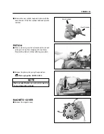
Отзывы: