7-13 CHASSIS
HANDLEBARS
◉
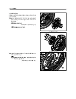
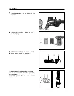
HANDLEBARS RIGHT SIDE PARTS
REMOVAL
●
Remove the right handlebar switches.
●
Disconnect the brake lamp switch lead wires
and remove the master cylinder. (Refer to page 7-
10)
●
Remove the handlebar balancer
①
and grip
②
.
◉
HANDLEBARS LEFT SIDE PARTS
REMOVAL
●
Remove the left handlebar switches.
●
Remove the handlebar balancer
③
and grip
④
.
●
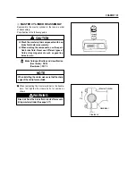
Remove the clutch lever holder.
●
Remove the clamp bolts and detach the handle-
bar holders.
●
Remove the handlebar.
◉
REMOUNTING
Perform the remounting work in the reverse order of
the removal procedures while observing the fol-
lowing instructions.
●
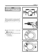
Install the handlebars with the punch mark
⑤
aligned with the handlebar clamp as shown.
●
Tighten the handlebar clamp bolts to the speci-
fied torque.
Handlebar clamp bolts
: 18~28 N
∙
m (1.8 ~2.8 kg
∙
m)
①
②
④
③
⑤
Содержание GT 650
Страница 5: ...NOTE Difference between photographs and actual motorcycles depends on the markets ...
Страница 13: ...1 7 GENERAL INFORMATION EXTERIOR ILLUSTRATION ...
Страница 102: ...CARBURETOR 4 3 FUEL SYSTEM ...
Страница 138: ...LAMP HEADLAMP TURN SIGNAL LAMP TAIL BRAKE LAMP ELECTRICAL SYSTEM 6 16 ...
Страница 158: ...7 15 CHASSIS FRONT FORK ...
Страница 210: ...Prepared by HYOSUNG MOTORS MACHINERY INC 2nd Ed JUN 2004 Manual No 99000 94810 Printed in Korea ...

