3-47 ENGINE
●
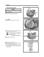
Install the clutch cover, and tighten the clutch cover
bolts securely.
●
Install the clutch release arm as following:
①
Turn the clutch release shaft toward(This time,
mark on the shaft align outside contact line the
stopper screw) the right.
②
Install that the release camshaft notch mark align
matching mark of the crankcase as shown in the
right figure.
THREAD LOCK
“
1324
”
◉
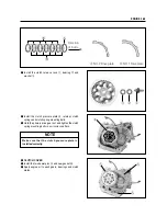
STATOR
●
Apply a small quantity of THREAD LOCK
“
1324
”
to
the threaded parts of screws.
THREAD LOCK
“
1324
”
◉
STARTER CLUTCH
●
When installing the starter clutch and rotor, apply the
THREAD LOCK
“
1324
”
to the bolts and tighten to
the specified torque.
Engine oil drain plug
: 21 N
∙
m (2.1 kg
∙
m)
◉
OIL DRAIN PLUG
●
Tighten the oil drain plug to the specified torque.
Starter clutch bolt
: 23~28 N
∙
m (2.3~2.8 kg
∙
m)
Crankcase
matching mark
Clutch release arm
Clutch release
arm bolt
Stopper screw
Release
camshaft notch
mark
Содержание GT 650
Страница 5: ...NOTE Difference between photographs and actual motorcycles depends on the markets ...
Страница 13: ...1 7 GENERAL INFORMATION EXTERIOR ILLUSTRATION ...
Страница 102: ...CARBURETOR 4 3 FUEL SYSTEM ...
Страница 138: ...LAMP HEADLAMP TURN SIGNAL LAMP TAIL BRAKE LAMP ELECTRICAL SYSTEM 6 16 ...
Страница 158: ...7 15 CHASSIS FRONT FORK ...
Страница 210: ...Prepared by HYOSUNG MOTORS MACHINERY INC 2nd Ed JUN 2004 Manual No 99000 94810 Printed in Korea ...


