


7-21 CHASSIS
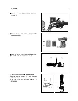
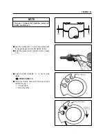
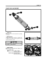
●
Install the front fork cap bolt to the outer tube tem-
porarily.
●
Set the front fork to the lower bracket temporarily,
tighten the front fork cap bolt
④
to the specified
torque.
Front fork cap bolt
: 30~40N
∙
∙
m (3.0~4.0 kg
∙
∙
m)
●
With the front fork upper face contacted with the han-
dlebar holder, tighten the front fork upper and lower
clamp bolts to the specified torque.
Front fork upper clamp bolt
: 22~35N
∙
∙
m (2.2~3.5 kg
∙
∙
m)
Front fork lower clamp bolt
: 22~35N
∙
∙
m (2.2~3.5 kg
∙
∙
m)
④
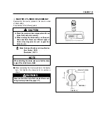
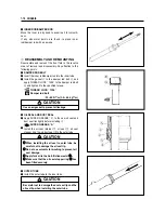
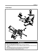
■
FRONT FORK INNER ROD LOCK NUT
●
Adjust the height
�
of the inner rod threads by turn-
ing the lock nut
①
at 11mm(0.43 in) as shown in
illustration.
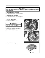
■
FORK SPRING
●
Install the fork spring as shown in the illustration.
●
Install the spring retainer and the spacer.
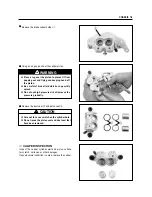
■
FRONT FORK CAP BOLT
●
Hold the cap bolt
②
and tighten the lock nut
③
to the
specified torque.
Inner rod lock nut
: 17.5~22.5N
∙
∙
m (1.75~2.25 kg
∙
∙
m)
Upper side
②
③
↓
↑
↓
↑
Содержание GT 650
Страница 5: ...NOTE Difference between photographs and actual motorcycles depends on the markets ...
Страница 13: ...1 7 GENERAL INFORMATION EXTERIOR ILLUSTRATION ...
Страница 102: ...CARBURETOR 4 3 FUEL SYSTEM ...
Страница 138: ...LAMP HEADLAMP TURN SIGNAL LAMP TAIL BRAKE LAMP ELECTRICAL SYSTEM 6 16 ...
Страница 158: ...7 15 CHASSIS FRONT FORK ...
Страница 210: ...Prepared by HYOSUNG MOTORS MACHINERY INC 2nd Ed JUN 2004 Manual No 99000 94810 Printed in Korea ...


