


UPS5000-S-880 kVA
User Manual (CMI)
3 Installation
Issue 02 (2020-01-10)
Copyright © Huawei Technologies Co., Ltd.
58
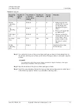
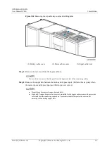
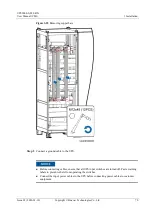
Figure 3-12
Installing the soft copper bars numbered 52
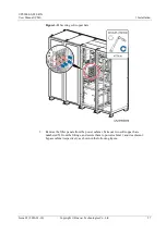
Step 10
Insert the cable terminals in the bypass cabinet into the corresponding ports on the system
signal interface board in power cabinet 1. The system signal interface board is located at the
rear of power cabinet 1. It can be seen if the cabinet rear cover is removed.
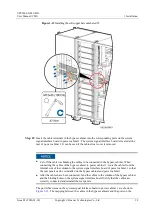
Cut off the cable ties binding the cables to be connected in the bypass cabinet. When
connecting the cables of the bypass cabinet to power cabinet 1, route the cables from the
internal side of the column to the system signal interface board of power cabinet 1 so that
the rear panels can be reinstalled on the bypass cabinet and power cabinet 1.
After the cables have been connected, bind the cables to the column of the bypass cabinet
and the binding holes on the system signal interface board. Verify that the cables are
correctly connected and reinstall the rear panels.
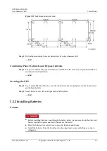
The port silk screens on the system signal interface board in power cabinet 1 are shown in
. The mapping between the cables in the bypass cabinets and the ports on the