


Removal and Replacement Procedures 61
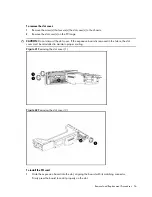
1.
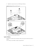
Align the system board I/O connectors to their openings and slide the system into place. The
nine screw holes on the chassis should align with the system board.
2.
Fasten the nine screws on the system board to secure the system board to the chassis.
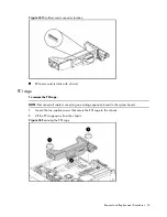
Figure 50
Installing the system board
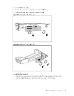
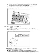
Power Supply Unit (PSU)
Located on the rear panel of the server power supply is a standard autoranging 750-watt PSU with
PFC (power factor correction) function.
Figure 51
Power supply unit
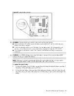
WARNING:
Take note of the following reminders to reduce the risk of personal injury from electric
shock hazards and/or damage to the equipment.
•
Installation of power supply units should be referred to individuals who are qualified to service server
systems and are trained to deal with equipment capable of generating hazardous energy levels.
Содержание ProLiant DL180 G
Страница 1: ...HP ProLiant DL180 Server Maintenance and Service Guide Part number 448409 001 First edition July 2007 ...
Страница 12: ...Customer self repair 12 ...
Страница 13: ...Customer self repair 13 ...
Страница 14: ...Customer self repair 14 ...
Страница 15: ...Customer self repair 15 ...
Страница 19: ...Illustrated parts catalog 19 ...
Страница 79: ...Diagnostic tools and Setup Utilities 79 Main Menu Figure 67 Main menu of the BIOS Setup Utility ...
Страница 82: ...Diagnostic tools and Setup Utilities 82 ...
Страница 83: ...Diagnostic tools and Setup Utilities 83 Security Menu Figure 71 Security menu of the BIOS Setup Utility 1 ...
Страница 84: ...Diagnostic tools and Setup Utilities 84 Figure 72 Security menu of the BIOS Setup Utility 2 ...


