


Removal and Replacement Procedures 33
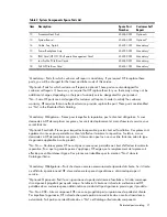
Table 4
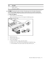
Cable Connections
Cable
To
System Board Designator
SATA 1 Connector
System board
P17
SATA 5 Connector
System board
P12
Power Supply Management Interface
Connector
System board
J55
External HDD LED Connector
System board
P23
Front USB 2.0 Cable Header
System board
P20
5-pin System Fan 4 Header
System board
P21
Internal USB 2.0 Header for Tape
Drive
System board
J36
Internal USB 2.0 Port
System board
J32
PATA ODD
System board
P25
5-pin System Fan 3 Connector
System board
P22
8-pin Power Connector
System board
P24
5-pin System Fan 1 Connector
System board
P8
24-pin Power Connector
System board
P7
4-pin Power Connector
System board
P6
5-pin System Fan 2 Header (with
extension cable)
System board
P4
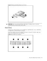
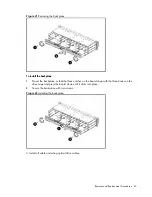
Drive Bay Configuration
The server supports a maximum of nine drive bays – eight bays for 1-inch hard disk drives and one
drive bay for an optical media drive.
Содержание ProLiant DL180 G
Страница 1: ...HP ProLiant DL180 Server Maintenance and Service Guide Part number 448409 001 First edition July 2007 ...
Страница 12: ...Customer self repair 12 ...
Страница 13: ...Customer self repair 13 ...
Страница 14: ...Customer self repair 14 ...
Страница 15: ...Customer self repair 15 ...
Страница 19: ...Illustrated parts catalog 19 ...
Страница 79: ...Diagnostic tools and Setup Utilities 79 Main Menu Figure 67 Main menu of the BIOS Setup Utility ...
Страница 82: ...Diagnostic tools and Setup Utilities 82 ...
Страница 83: ...Diagnostic tools and Setup Utilities 83 Security Menu Figure 71 Security menu of the BIOS Setup Utility 1 ...
Страница 84: ...Diagnostic tools and Setup Utilities 84 Figure 72 Security menu of the BIOS Setup Utility 2 ...


