


Removal and Replacement Procedures 32
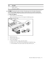
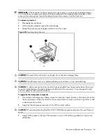
Figure 5
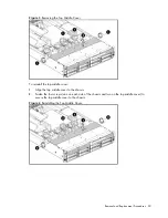
Unplugging power cables
Cable Connections
The following table provides information about switching power supply cable connector labels.
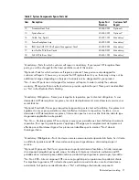
Table 3
Switching Power Supply Cable connections
Cable To
Cable
Designator
Switching Power Supply
System board 24-pin power connector
P1
Switching Power Supply
System board 8-pin power connector
P2
Switching Power Supply
System board 4-pin power connector
P3
Switching Power Supply
Backplane
P4
Switching Power Supply
Backplane
P5
Switching Power Supply
Optical disc drive
CD
Switching Power Supply
System board Power Supply
Management Interface connector
RPS
The following table provides the system board designators that various cables plug into. For more
detailed information about system board components, see System board components on page 67.
Table 4
Cable Connections
Cable
To
System Board Designator
18-Pin Front Panel Connector
System board
P10
SATA 4 Connector
System board
P13
SATA 2 Connector
System board
P14
SATA 6 Connector
System board
P15
SATA 3 Connector
System board
P10
Содержание ProLiant DL180 G
Страница 1: ...HP ProLiant DL180 Server Maintenance and Service Guide Part number 448409 001 First edition July 2007 ...
Страница 12: ...Customer self repair 12 ...
Страница 13: ...Customer self repair 13 ...
Страница 14: ...Customer self repair 14 ...
Страница 15: ...Customer self repair 15 ...
Страница 19: ...Illustrated parts catalog 19 ...
Страница 79: ...Diagnostic tools and Setup Utilities 79 Main Menu Figure 67 Main menu of the BIOS Setup Utility ...
Страница 82: ...Diagnostic tools and Setup Utilities 82 ...
Страница 83: ...Diagnostic tools and Setup Utilities 83 Security Menu Figure 71 Security menu of the BIOS Setup Utility 1 ...
Страница 84: ...Diagnostic tools and Setup Utilities 84 Figure 72 Security menu of the BIOS Setup Utility 2 ...


