


Removal and Replacement Procedures 42
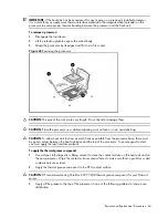
Item
Description
1 Cable
connectors
2 10-pin
power
connector
WARNING:
Ensure that the system is powered off and all power sources have been disconnected
from the server. Voltages are present at various locations within the server whenever an AC power
source is connected. This voltage is present even when the main power switch is in the off position.
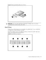
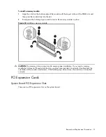
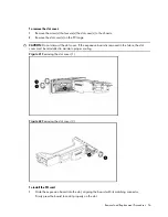
To remove the backplane:
1.
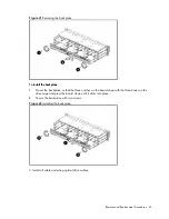
Remove all drives out of the drive bays.
Refer to the Hard Drives sections in this chapter for detailed procedures.
Figure 20
Removing the drives
2.
Remove the top cover.
3.
Remove the top middle cover.
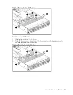
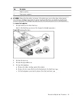
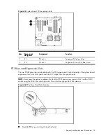
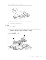
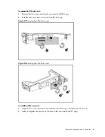
4.
Remove the backplane.
a.
Remove all cables including optical drive cables.
b.
Remove the two screws that secure the backplane to the hard drive cage.
c.
Pull the backplane up and out to release it from the hard drive cage.
Содержание ProLiant DL180 G
Страница 1: ...HP ProLiant DL180 Server Maintenance and Service Guide Part number 448409 001 First edition July 2007 ...
Страница 12: ...Customer self repair 12 ...
Страница 13: ...Customer self repair 13 ...
Страница 14: ...Customer self repair 14 ...
Страница 15: ...Customer self repair 15 ...
Страница 19: ...Illustrated parts catalog 19 ...
Страница 79: ...Diagnostic tools and Setup Utilities 79 Main Menu Figure 67 Main menu of the BIOS Setup Utility ...
Страница 82: ...Diagnostic tools and Setup Utilities 82 ...
Страница 83: ...Diagnostic tools and Setup Utilities 83 Security Menu Figure 71 Security menu of the BIOS Setup Utility 1 ...
Страница 84: ...Diagnostic tools and Setup Utilities 84 Figure 72 Security menu of the BIOS Setup Utility 2 ...


