background image

Chapter 4

Installing Additional Components and Configuring

Hot-Plug PCI-X

60

Step 10.

Push the HP Server all the way back into the rack until it stops.

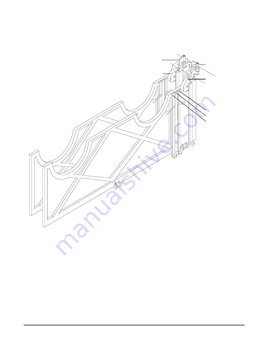
Figure 4-16PCI-X OLX Divider Layout

PCI-X card latch
closed position

Manual retention 
latch—closed

PCI-X card latch
open position

Manual retention 
latch—open

Power LED
light pipe
Attention button
Attention LED 
light pipe

Содержание Integrity rx4640

Страница 1: ...grity rx4640 Operation and Maintenance Guide Regulatory Model Number RSVLA 0201 Version 3 0 Manufacturing Part Number rx4640_OpMaint April 2004 U S A Copyright 2003 2004 Hewlett Packard Development Company L P ...

Страница 2: ...nted in the U S A Reproduction adaptation or translation of this document without prior written permission is prohibited except as allowed under the copyright laws Related Documents The HP Server Documentation CD ROM has been provided with your server It contains a complete documentation set for the server including localized versions of key documents Included on the CD ROM are the Site Preparatio...

Страница 3: ...et Card LAN LEDs 27 3 External Connectors Connector Pinouts 29 Universal Serial Bus USB Ports 29 VGA Port 30 Serial Ports 31 Management Processor LAN Port 31 Additional Ports on Accessory Boards 32 4 Installing Additional Components and Configuring Installing Power Supplies and Disk Drives 35 Installing Hot Swap Power Supply Units PSU 35 Installing Hot Plug Disk Drives 38 Installing Processors and...

Страница 4: ... 91 help 91 baud 93 boottest 93 cpuconfig 94 default 95 errdump 95 info 96 lanaddress 100 monarch 100 pdt 101 sysmode 102 Specifying SCSI Parameters 103 Using the SCSI Setup Utility 103 Management Processor 109 Accessing the Management Processor 109 Management Processor Command Interface 110 Management Processor Commands 111 Reset BMC Passwords 112 Configure Serial Port Parameters 112 Certificate ...

Страница 5: ...stem 120 6 Troubleshooting Troubleshooting Tips 123 Troubleshooting Methodology 123 Possible Problems 125 The system will not power up 125 The system will not boot 125 The system has intermittent failures 126 The system LED or Diagnostic LEDs are not on and no error messages appear 126 Power goes off on the server and does not come back on 127 Troubleshooting Using LED Indicators 128 Front Control...

Страница 6: ...Extender Board 151 Removing a Memory Extender Board 151 Replacing a Memory Extender Board 153 System Memory DIMMs 154 Removing System Memory DIMMs 154 Installing Memory DIMMs 154 Processor Extender Board 160 Removing the Processor Extender Board 160 Replacing the Processor Extender Board 161 Processors 162 Installing Processors 162 Removing a Processor 162 Replacing a Processor 163 Hot Swap Chassi...

Страница 7: ...pplies 205 Power Supply Load Order 205 Removing a Hot Swap Power Supply 205 Replacing a Hot Swap Power Supply 206 Power Distribution Board 207 Removing the Power Distribution Board 208 Replacing the Power Distribution Board 209 DVD Drive 210 Removing a DVD Drive 211 Replacing a DVD Drive 211 DVD I O Board 213 Removing a DVD I O Board 214 Replacing a DVD I O Board 215 Display Board 216 Removing the...

Страница 8: ...Contents 8 ...

Страница 9: ...ation in Slots 1 and 2 39 Figure 4 5 Disk Drive Installation in Slot 2 39 Figure 4 6 Volume Filler Installation in Slot 2 40 Figure 4 7 Removing the Processor Extender Board 42 Figure 4 8 Removing Processor Extender Board 43 Figure 4 9 Processor Cable Placed Correctly 44 Figure 4 10 Processor Cable Placed Incorrectly 44 Figure 4 11 Installing Processor on Extender Board Example 46 Figure 4 12 16 D...

Страница 10: ...r Board 167 Figure 7 16 Hot Swap I O Chassis Fans Removal and Replacement 169 Figure 7 17 Hot Swap Power Supply Chassis Fan Removal and Replacement 170 Figure 7 18 I O Board Locking Lever 173 Figure 7 19 I O Baseboard 174 Figure 7 20 I O Baseboard Select Switches 175 Figure 7 21 Slot ID Numbering 182 Figure 7 22 PCI X OLX Divider Layout 184 Figure 7 23 Inserting PCI X Card 185 Figure 7 24 OLX Divi...

Страница 11: ...ut all external connectors plugs and their pinouts Chapter 4 Installing Additional Components and Configuring Use this chapter to learn how to install additional hot swap power supplies hot swap disk drives memory DIMMs processors and PCI X cards Also learn how to configure your management processor and boot your HP Server Chapter 5 Utilities Use this chapter to learn how to navigate in the EFI an...

Страница 12: ...e send any comments by contacting us at http docs hp com assistance index html Please include document title manufacturing part number and any comment error found or suggestion for improvement you have concerning this document Where to Get Help For online access to technical support information self solve tools online assistance community forums of IT experts broad multivendor knowledge base and m...

Страница 13: ...N RS232 or web interface to monitor the server How many processors DIMMs and PCI cards have been installed What versions of processor memory and PCI cards are used and where are they installed What accessories are installed Step 4 Determine the following Which firmware versions are in use When did the problem start Have recent changes been made to the system Which operating system and version is i...

Страница 14: ...Chapter 1 About This Document Where to Get Help 14 ...

Страница 15: ...Introduction This chapter describes the controls ports and indicators found on the front panel rear panel and internal locations of the hp Integrity rx4640 Server The hp Integrity rx4640 Server comes in either rack mount or pedestal configurations ...

Страница 16: ...icators Front Panel 16 Front Panel The front panel of the hp Integrity rx4640 Server provide the controls and indicators commonly used for operation Figure 2 1 Front View with Bezel Figure 2 2 Accessing the Control Panel Control Panel ...

Страница 17: ...ult Flashing at 2 Hz Red Flashing Red Hard fault system halted System Off Off N A Off System off Power On Steady Green Green Power normal Power On Steady Yellow Flashing Yellow Housekeeping voltage present Power Off Off Off Off Power off Disk LED Flashing at rate of disk activity Green Flashing Green Disk activity Thermal LED OK Steady Green Green Thermal OK Thermal LED Warning Flashing at 1 Hz Ye...

Страница 18: ...ccessed Figure 2 4 Hot Swap Disk Drive LED Indicators Table 2 2 Switch Button LED Definitions Button Switch Description Power Button The power switch turns the HP Server power on or off If sleep states are available it also transitions between power on and sleep states Sleep states are NOS dependent and only available if your NOS supports power management based on the ACPI Advanced Configuration a...

Страница 19: ...or LED for temperature The LEDs are normally off The appropriate LED is turned on when an error is detected or a replacement part is required Status LED Solid Amber Amber Green Blank Drive fault Missing management board or jumper cable For all HDD on SCSI bus A and or B Drive Slot normal drive present Pass through mode Table 2 4 DVD Drive LED Definitions LED Description Activity LED Flashing green...

Страница 20: ... 6 QuickFind Diagnostic Panel Table 2 5 QuickFind Diagnostic Panel LEDs Item LED 0 LED 1 LED 2 LED 3 Details Processor Socket 0 Socket 1 Socket 2 Socket3 If the System LED on front panel is in the attention or fault state and the processor LED is lit then the processor or voltage regulator has failed the processor module in the specified socket needs to be replaced If the thermal LED is in the war...

Страница 21: ... mismatched DIMM Check Power Supply n a n a n a One of the power supply or power supply fans has failed replace the power supply The faulty power supply LED located on power supply will be lit Memory Config Error n a n a n a The DIMMs in a rank are mismatched All the DIMMs in the specified rank 0 7 will be lit Processor Config Error n a n a n a The processors are mismatched replace mismatched proc...

Страница 22: ...ble 2 6 I O Baseboard LEDs Buttons and Sensors LED Button Color Status Condition 12V VRM Power LED Green On 12V VRM is functioning 5V VRM Power LED Green On 5V VRM is functioning PCI Attention LED 6X PCI Attention Button Doorbell 6X PCI Power LED 6X PCI Attention LED 6X 3 3VSB Power LED BMC Reset Button 12V VRM LED 3 3V VRM LED Locator Button LED 5V VRM LED MP Soft Reset Button MP Self Test LED MP...

Страница 23: ...t card LAN 3 3V VRM Power LED Green On 3 3V VRM is functioning MP Heartbeat Green Blinking The management processor is functioning correctly MP Self Test LED Amber On Off The management processor is executing the internal self test The management processor has passed the internal self test BMC Heartbeat Green Blinking The baseboard management controller is functioning correctly 3 3VSB Power LED Gr...

Страница 24: ...Chapter 2 Controls Ports and Indicators Rear Panel 24 PCI slots 3 8 Figure 2 8 Rack Mount and Pedestal Rear View Gigabit Ethernet LAN LEDs MP LAN LEDs 6 PCI Attention LEDs Locator Button LED ...

Страница 25: ...ly Status LED Table 2 7 Power Supply Status LED Power LED Green Predict Fail LED Amber Fail LED Amber Status Off Off Off No AC power applied to all PSUs Off Off On No AC power applied to this PSU only Blinking Off Off AC present standby outputs on On Off Off PSU DC outputs on and OK Off Off On Power supply failure On Blinking Off Predictive failure PSU about to fail because of poorly performing fa...

Страница 26: ...ided on the rear panel of the server Another single blue LED and button is on the front control panel that enables disables the locator function See Figure 2 10 MP LAN LEDs Table 2 8 MP LED Status Descriptions LED Condition Status 10M amber On Linked at 10MBps no activity 10M amber Blinking Linked at 10MBps activity present 100M green On Linked at 100MBps no activity 100M green Blinking Linked at ...

Страница 27: ...nk and 1 LAN activity that signal link speed and activity Figure 2 11 Core I O LAN Port LEDs Table 2 9 Core LED Status Descriptions LED Condition Status Activity Green on Linked no activity Activity Green off No link Activity Green blinking Linked activity present 1000 Green on Link speed 1000 MBps 100 Green on Link speed 100 MBps 10 Green on Link speed 10 MBps RJ 45 Connector 1000 100 Activity 10...

Страница 28: ...Chapter 2 Controls Ports and Indicators Rear Panel 28 ...

Страница 29: ...pter card in slot 1 and the Gigabit Ethernet card in slot 2 are factory installed Figure 3 1 Rear View Universal Serial Bus USB Ports Figure 3 2 USB Port Connector Table 3 1 USB Pinouts Pin Number Signal Description 1 5VDC 2 MR HBA Ultra 3 SCSI 68 Pin Gigabit Ethernet LAN Port 3 Serial Ports VGA Port Management Processor LAN Port USB Ports Local Ax Remote 1 2 3 4 1 2 3 4 ...

Страница 30: ...ber Signal Description Pin Number Signal Description 1 Red 9 5VDC 2 Green 10 Sync return ground 3 Blue 11 Not used 4 Not used 12 Monitor ID bit 1 5 Video Self Test ground 13 Horizontal sync 6 Red return ground 14 Vertical sync 7 Green return ground 15 Video ID bit 2 8 Blue return ground Table 3 1 USB Pinouts Continued Pin Number Signal Description ...

Страница 31: ...rocessor Port Table 3 3 Serial Port Pinouts Pin Number Signal Description 1 Data carrier detect 2 Receive data 3 Transmit data 4 Data Term ready 5 Ground 6 Data set ready 7 Request to send 8 Clear to send 9 Ring indicator Table 3 4 Management Processor LAN Port Pinouts Pin Number Signal Description 1 TXP 2 TXN 3 RXP 5 4 3 2 1 9 8 7 6 Green 1 Yellow 8 ...

Страница 32: ...ernet LAN Port Figure 3 6 LAN Port 4 Not used 5 Not used 6 RXN 7 Not used 8 Not used Table 3 5 LAN Port Pinouts Pin Number Signal Description 1 RXP 2 RXN 3 TXP 4 Not used 5 Not used 6 TXN 7 Not used 8 Not used Table 3 4 Management Processor LAN Port Pinouts Continued Pin Number Signal Description 1 8 ...

Страница 33: ...umber Signal Description Pin Number Signal Description 1 S1 DB 12 35 S35 DB 12 2 S2 DB 13 36 S36 DB 13 3 S3 DB 14 37 S37 DB 14 4 S4 DB 15 38 S38 DB 15 5 S5 DB P1 39 S39 DB P1 6 S6 DB 0 40 S40 DB 0 7 S7 DB 1 41 S41 DB 1 8 S8 DB 2 42 S42 DB 2 9 S9 DB 3 43 S43 DB 3 10 S10 DB 4 44 S44 DB 4 11 S11 DB5 45 S45 DB 5 12 S12 DB 6 46 S46 DB 6 13 S13 DB 7 47 S47 DB 7 14 S14 DB P 48 S48 DB P 15 S15 49 S49 16 S...

Страница 34: ...K 25 S25 RST 59 S59 RST 26 S26 MSG 60 S60 MSG 27 S27 SEL 61 S61 SEL 28 S28 C D 62 S62 C D 29 S29 REQ 63 S63 REQ 30 S30 I O 64 S64 I O 31 S31 DB 8 65 S65 DB 8 32 S32 DB 9 66 S66 DB 9 33 S33 DB 10 67 S67 DB 10 34 S34 DB 11 68 S68 DB 11 Table 3 6 SCSI Port Pinouts Continued Pin Number Signal Description Pin Number Signal Description ...

Страница 35: ...evice does not require interaction with the operating system before the device is removed from or installed into the server The AC power to the server does not have to be off to install a hot swap power supply Figure 4 1 Front View Installing Hot Swap Power Supply Units PSU Power Supply Load Order The supported configuration of an hp Integrity rx4640 Server requires a minimum of one 200 240 VAC po...

Страница 36: ...rver To install a hot swap power supply perform the following steps Step 1 If rack mounted slide the HP server out from the rack until it stops See Accessing a Rack Mounted Server on page 141 Step 2 Remove the metal cover from slot P 1 Grasp the metal cover and pull straight out Step 3 Supporting the PSU with both hands slide it into slot P 1 until it plugs into the socket on the internal power su...

Страница 37: ...stalling Additional Components and Configuring Installing Power Supplies and Disk Drives 37 Step 6 If rack mounted slide the HP server back into the rack until it stops Figure 4 2 Hot Swap Power Supply in P 0 Slot ...

Страница 38: ...isk Drives One additional hot plug disk drive may be added to your hp Integrity rx4640 Server in slot 2 Always use low profile disk drives 1 0 height in your HP Server To install a hot plug disk drive perform the following steps Step 1 Slide the hot plug hard disk into slot 1 until it is seated Step 2 Close the drive ejector handle by pushing it down until it clicks ...

Страница 39: ... and Configuring Installing Power Supplies and Disk Drives 39 The hot plug disk drive is now correctly installed Figure 4 4 Disk Drive Installation in Slots 1 and 2 Figure 4 5 Disk Drive Installation in Slot 2 Slot 2 SCSI ID 1 Slot 1 SCSI ID 0 ...

Страница 40: ...connected This voltage is present even when the main power switch is in the off position Ensure that the system is powered down and all power sources have been disconnected from the server prior to attempting the following procedures Failure to observe this warning could result in personal injury or damage to equipment CAUTION Observe all ESD safety precautions before attempting this procedure Fai...

Страница 41: ...sor modules are attached to the processor extender board which is located under the top cover in the top service bay directly under the memory extender board The processor extender board can hold between one and four processor modules CPU 0 and CPU 1 are located on the top of the processor extender board and CPU 2 and CPU 3 are located on the bottom Processor modules must be installed in a specifi...

Страница 42: ...wing instructions carefully and refer to Figure 4 11 Installing Processor on Extender Board Example for a complete understanding of this process Step 1 If rack mounted slide the HP Server out from the rack until it stops See Accessing a Rack Mounted Server on page 141 Step 2 Remove the front bezel See Front Bezel on page 144 Step 3 Remove the front cover See Removing the Front Cover on page 145 St...

Страница 43: ...Carefully lower the processor without the sequencer clamp onto the processor socket Align the pins on the bottom of the heatsink to the slots in the retention frame on the extender board as shown in Figure 4 11 Installing Processor on Extender Board Example CAUTION Test the alignment of the assembly to the socket by gently moving the assembly back and forth with the palm of your hand you should fe...

Страница 44: ...able into place under the heatsink See Figure 4 9 Processor Cable Placed Correctly and Figure 4 10 Processor Cable Placed Incorrectly Figure 4 9 Processor Cable Placed Correctly Figure 4 10 Processor Cable Placed Incorrectly Step 9 Lock the assembly to the socket by rotating the cam on the socket 180 degrees clockwise using a 2 5 mm driver Allen wrench Heatsink Cable is placed correctly and is und...

Страница 45: ...et on the extender board Step 11 Place the sequencer frame over the processor Step 12 Using the supplied torx T15 driver tighten the 6 T15 shoulder screws until they just bottom out Follow the tightening sequence shown in Figure 4 11 Installing Processor on Extender Board Example CAUTION Do not overtighten the 6 shoulder screws they may shear off if overtightened Stop tightening the shoulder screw...

Страница 46: ...ple Tightening sequence for 6 shoulder screws AB371A or AB372A 1 2 3 4 5 6 AB373A 3 4 1 2 5 6 DO NOT OVERTIGHTEN Torx T15 Use supplied wrench for tightening shoulder screws 2 5MM Allen Align pins on heatsink with slots in frame Slots shown are atCPU socket 1 for clarity Processor shown is being mounted on socket 0 per CPU load order Slots Slots Power cable protected by plastic sleeve 1 2 3 4 5 6 S...

Страница 47: ...may insert additional DIMMs into both sixteen and thirty two DIMM boards When adding DIMMs you must use a minimum of four like sized DIMMs in the next available quad Supported DIMM Sizes Supported DIMM sizes are 256MB 512MB 1GB 2GB Dissimilar DIMM sizes may be used across the entire extender board but all four DIMMs in each quad must match For cooling purposes DIMM fillers must be used in unused s...

Страница 48: ...al 2 fillers in quads 1 2 and 3 All quads filled 8 DIMMs in quads 0 and 1 4 fillers total 2 fillers in quads 2 and 3 All quads filled 12 DIMMs in quads 0 1 and 2 2 fillers total 2 fillers in quads 3 All quads filled 16 DIMMs in quads 0 1 2 and 3 No fillers required Table 4 3 DIMM Filler Requirements for 32 DIMM Extender Board 32 DIMM Extender Board DIMMs Loaded Fillers requireda 4 DIMMs in quad 0 ...

Страница 49: ... quads 0 1 2 3 and 4 4 fillers total 2 fillers in quads 5 7 quad 6 remains unfilled 24 DIMMs in quads 0 1 2 3 4 and 5 No fillers required 28 DIMMs in quads 0 1 2 3 4 5 and 6 No fillers required 32 DIMMs in quads 0 1 2 3 4 5 6 and 7 No fillers required a One DIMM filler board covers two DIMM adjacent slots Table 4 3 DIMM Filler Requirements for 32 DIMM Extender Board Continued 32 DIMM Extender Boar...

Страница 50: ...lling Additional Components and Configuring Installing Processors and Memory 50 Figure 4 12 16 DIMM Extender Board Minimum Configuration Figure 4 13 32 DIMM Extender Board Minimum Configuration DIMM Filler DIMM Filler ...

Страница 51: ...ont Cover on page 145 Step 4 Press each latch on the two extraction levers located on each side of the memory extender board Step 5 Pull on the extraction levers to unplug the memory extender board from the socket located on the midplane riser board and remove the memory extender board from the chassis Installing DIMMs To install DIMMs perform the following steps Step 1 Align the DIMM with the soc...

Страница 52: ...e positioned in the outward unlocked position Step 2 Align the memory extender board with the left and right chassis guide slots Step 3 Slide the memory extender board in until it begins to seat in the socket located on the midplane riser board Step 4 Push the extraction levers inward to the locked position in order to fully plug in the memory extender board into the midplane riser board Step 5 Re...

Страница 53: ... OL A operation This is the equivalent of an OL R operation Online Deletion OL D You can remove an existing PCI X expansion card This operation is different from OL R because there are no restrictions placed on the type of replacement card that you can use In this operation the drivers are also completely removed from the slot NOTE HP UX 11i v2 does not support OL D It does support OL R PCI X Slot...

Страница 54: ... Advanced Server 2 1 operating systems PCI X Hardware and Software Interfaces The following table shows what hot plug hardware and software interfaces are available on HP UX 11i v2 Windows Server 2003 Enterprise Edition and Linux Red Hat Advanced Server 2 1 operating systems Table 4 4 Hot Plug Operation and OS Compatibility Hot Plug Operation HP UX 11i v2 Windows Server 2003 Enterprise Edition Lin...

Страница 55: ...ed by the configuration of the occupied slot If the new card has a slower capability than the current bus configuration it will be rejected If the new card has a faster capability than the current bus configuration it will only run at the bus mode and frequency of the current bus configuration slower 1 If you have a 66 MHz card in slot 3 and you hot plug insert a 33 Mhz card into slot 4 then the o...

Страница 56: ...r Shared Slotsa a NOTE The conditions described in this table apply only to shared slots slots 3 4 bus 2 and 5 6 bus 3 Slots 7 and 8 are not shared slots Current PCI Bus Mode and Frequency for the Shared Slot Cards to be installed PCI 33 PCI 66 PCI X 66 PCI X 133 PCI 33 MHz Compatibleb b Compatible card is accepted and runs at frequency shown Compatible 2nd note New card running at PCI 33 Compatib...

Страница 57: ...is configuration the Linux driver will not initialize the new card CAUTION Do not use more than 3 RAID cards in any of the slots on your hp Integrity rx4640 Server System power limitations restrict the use of more than 3 RAID cards per system Figure 4 15 Slot ID Numbering PCI X Bus 1 PCI X Bus 2 PCI X Bus 3 PCI X Bus 4 PCI X Bus 5 Slot ID Number Amber attention LEDs 6x Green power LEDs 6x Amber at...

Страница 58: ...e Removing the Top Cover on page 147 Step 3 If the power LED is steady on power to slot is on go to step 4 If the power LED is steady off power to slot is off go to step 5 Step 4 To turn off power to the slot pull up on the manual retention latch MRL located on the OLX divider The power LED goes to steady off See Figure 4 16 on page 60 CAUTION Do not pull up on the MRL of a powered on occupied slo...

Страница 59: ...stalling Additional Components and Configuring Hot Plug PCI X 59 NOTE After pushing the attention button you have 5 seconds to cancel the operation by pushing the attention button again Step 9 Replace the top cover ...

Страница 60: ... Push the HP Server all the way back into the rack until it stops Figure 4 16PCI X OLX Divider Layout PCI X card latch closed position Manual retention latch closed PCI X card latch open position Manual retention latch open Power LED light pipe Attention button Attention LED light pipe ...

Страница 61: ... Online Deletion OL D To delete a PCI X card from an occupied slot perform the following steps Step 1 If rack mounted slide the HP Server out from the rack until it stops See Accessing a Rack Mounted Server on page 141 Step 2 Remove the top cover from the chassis See Installing Processors and Memory on page 40 ...

Страница 62: ... a PCI X card into a populated slot perform the following steps Step 1 If rack mounted slide the HP Server out from the rack until it stops See Accessing a Rack Mounted Server on page 141 Step 2 Remove the top cover from the chassis See Installing Processors and Memory on page 40 Step 3 Press the attention button located on the OLX divider controls the affected slot the power LED starts to blink W...

Страница 63: ...ad Interface Card OL Support for HP UX Servers and Workstations Important Considerations B2355 90804 at http docs hp com 1 PCI X Bus Mode or Frequency Mismatch After you insert a PCI X card into the slot and push the attention button the power LED goes from blinking to steady off and stays at steady off This means that the system firmware has rejected the PCI X card and indicates either bus freque...

Страница 64: ...I X expansion cards using all the available power Check the power ratings of your existing PCI X cards A known cause of power loss is the use of more than 3 RAID cards in your system If the PCI X card cannot be powered off during a hot plug removal operation the attention button will turn steady on and the power LED will remain steady on CAUTION If your slot does not power off during a hot plug re...

Страница 65: ... present inside the HP Server Always remove AC power from the server and associated assemblies while working inside the unit Serious injury may result if this warning is not observed CAUTION Some restrictions apply to the mass storage devices that may be connected to your core I O SCSI HBA See Core I O Connections on page 71 If you convert your system to duplex configuration you may not install ex...

Страница 66: ... 2 Install the duplex board The duplex board is installed in the SCSI connector located nearest the disk drive cage The duplex board is shipped with a duplex board bracket attached When the duplex board is properly installed it is secured to the disk drive cage by the bracket and to the SCSI backplane board by the SCSI connector sockets See Figure 4 19 Installing the Duplex Board NOTE In simplex m...

Страница 67: ...ector on the SCSI backplane Press the board connector into the backplane connector NOTE When the duplex board is installed properly the board will be secured in the duplex board bracket The SCSI B cable will be connected to the connector at the immediate left of the duplex board Figure 4 19Installing the Duplex Board Step 3 Install the SCSI cable B to the SCSI backplane board See Figure 4 20 Insta...

Страница 68: ...o the duplex board installed in the previous step Figure 4 20Installing SCSI Cable B to the SCSI Backplane Step 4 The SCSI duplex conversion is completed by connecting the other end of SCSI cable B to the SCSI B channel connector on the SCSI adapter board See Figure 4 21 Installing SCSI Cable B to the SCSI Adapter Board Release the SCSI B cable from its stowed position within the chassis ...

Страница 69: ...al Components and Configuring Converting SCSI From Simplex to Duplex 69 Plug the SCSI cable B connector into the SCSI B channel connector located at the rear of the board Figure 4 21Installing SCSI Cable B to the SCSI Adapter Board ...

Страница 70: ...odules To return the server to operational configuration perform the following steps Step 1 Replace the processor extender board Step 2 Replace the memory extender board Step 3 Replace the front and top covers Step 4 Replace the front bezel Step 5 If rack mounted slide the HP Server back into the rack until it stops ...

Страница 71: ...sor is an independent support system for the server It provides a way for you to connect to your HP Server and perform administration or monitoring tasks for the server hardware The management processor controls power reset transfer of control TOC capabilities provides console access displays and records system events and can display detailed information about the various internal subsystems The m...

Страница 72: ...management processor enables such tasks as Verifying that the components are present and installed correctly Setting the LAN IP addresses Setting Terminal Parameters After powering on the terminal ensure the communications settings are as follows 8 none parity 9600 baud None receive None transmit If the terminal is a PC using Reflection 1 check or change these communications settings by performing...

Страница 73: ...dress of the management processor The management processor LAN port should now be configured with the appropriate IP address Step 5 Use the telnet command to connect to the management processor from a host on the local subnet Interacting with the Management Processor To interact with the management processor perform the following steps NOTE On initial system installation the MP has two default use...

Страница 74: ...n the IP address field is set at the factory The customer must provide the actual management processor LAN IP address Step 3 The current lc data is displayed When prompted to enter a parameter name A to modify All or Q to Quit enter A to select all parameters Step 4 The current IP address is displayed When prompted to enter a new value or Q enter the new IP address Step 5 The current host name is ...

Страница 75: ...n enter the MP command mode enter CM at the MP prompt Step 14 At the MP CM prompt enter LS to confirm the new LAN settings Step 15 Enter SA to enable disable web console and telnet access after the MP has been reset Figure 4 23The LC Command Screen MP CM lc ip 127 0 0 1 host uninitialized mask 255 255 255 0 gate 127 0 0 1 web 2003 New LAN Configuration modified value IP Address 127 0 0 1 MP Host N...

Страница 76: ...are upgrade HE Display help for menu or command ID System information IT Modify MP inactivity timers LC LAN configuration LOC Locater LED control LS LAN status MA Return to main menu MR Modem reset MS Modem status PC Remote power control PG Configure paging PR Power restore policy configuration PS Power management module status RB Reset BMC through toggle GPIO pin RS Request BMC to reset system th...

Страница 77: ...s SS System status of processor modules TC Transfer of control system reset through INIT signal TE Tell send a message to other users UC User configuration VT Display software trace VFP Virtual front panel WHO Display connected management processor users XD MP diagnostics and or reset Table 4 8 Management Processor Commands and Descriptions Continued Command Description ...

Страница 78: ... 12 00000010 B 6 20 PCI Bus Driver PciBus 1D 01020000 B X X 2 3 LSI Logic Ultra160 SCSI Driver PciRom Seg 00000000 1E 01020000 B X X 1 2 LSI Logic Ultra160 SCSI Driver PciRom Seg 00000000 23 00000109 D X X 1 HP Tachyon XL2 Fibre Channel Mass S PciRom Seg 00000000 2A 00000110 D X X 1 HP Tachyon XL2 Fibre Channel Mass S PciRom Seg 00000000 2E 00000029 D 2 Usb Ohci Driver UsbOhci 2F 00000010 B 2 3 US...

Страница 79: ...HCPv4 Driver PxeDhcp4 Step 2 Determine the controller handle associated with each of the two listed drivers 23 and 2A by typing the following command Shell drvcfg c 23 Configurable Components Drv 23 Ctrl 29 Lang eng Shell drvcfg c 2a Configurable Components Drv 2A Ctrl 2C Lang eng Step 3 Set the enumeration option for the driver 23 and controller 29 by typing the following command and selecting 1 ...

Страница 80: ...ci 2 0 Fibre WWN21000020375A5E5B Lun0 HD Part1 Si g7D930000 fs4 Acpi HWP0002 600 Pci 1 0 Scsi Pun4 Lun0 HD Part1 Sig70BEA120 E7EA 0 1C2 507B 9E5F8078F531 blk0 Acpi HWP0002 0 Pci 3 0 Ata Primary Master blk1 Acpi HWP0002 100 Pci 1 0 Scsi Pun1 Lun0 blk2 Acpi HWP0002 100 Pci 1 0 Scsi Pun1 Lun0 HD Part1 Sig11D3A260 CDCC 0 1C2 507B 9E5F8078F531 blk3 Acpi HWP0002 100 Pci 1 0 Scsi Pun1 Lun0 HD Part2 Sig11...

Страница 81: ...000020375AE6C1 Lun0 blk15 Acpi HWP0002 500 Pci 2 0 Fibre WWN21000020375A6215 Lun0 blk16 Acpi HWP0002 600 Pci 1 0 Scsi Pun4 Lun0 blk17 Acpi HWP0002 600 Pci 1 0 Scsi Pun4 Lun0 HD Part1 Sig70BEA120 E7EA 0 1C2 507B 9E5F8078F531 blk18 Acpi HWP0002 600 Pci 1 0 Scsi Pun4 Lun0 HD Part2 Sig70EC67E0 E7EA 0 1C2 F1B3 12714F758821 blk19 Acpi HWP0002 600 Pci 1 0 Scsi Pun4 Lun0 HD Part3 Sig7612C3E0 E7EA 0 1C2 D9...

Страница 82: ...OL Acpi HWP0002 100 Pci 1 0 Scsi Pun1 Lun0 HD Part1 S IA64_EFI Acpi HWP0002 100 Pci 1 1 Scsi Pun0 Lun0 HD Part1 Si IA64_EFI Acpi HWP0002 500 Pci 2 0 Fibre WWN21000020375AE714 L IA64_EFI Acpi HWP0002 500 Pci 2 0 Fibre WWN21000020375A5E5B L NO VOLUME LABEL Acpi HWP0002 600 Pci 1 0 Scsi Pun4 Lun0 HD P Removable Media Boot Acpi HWP0002 0 Pci 3 0 Ata Primary Maste Load File EFI Shell Built in Load File...

Страница 83: ...it Step 12 Enter a description of the new FC boot device and the data type Filename EFI HPUX HPUX EFI DevicePath Acpi HWP0002 500 Pci 2 0 Fibre WWN21000020375AE714 Lun0 HD Par t1 SigF7D00000 EFI HPUX HPUX EFI IA 64 EFI Application 05 05 03 04 54p 425 747 bytes Enter New Description FC Boot Disk New BootOption Data ASCII Unicode strings only with max of 240 characters Enter BootOption Data Type A A...

Страница 84: ...Chapter 4 Installing Additional Components and Configuring Fibre Channel FC Boot Configuration 84 System Configuration Menu Use and v to change option s Use Enter to select an option ...

Страница 85: ... is attached and in the closed position you will need to open the small door on the front bezel to gain access to the power switch If the autoboot function is enabled the system will boot to the installed operating system If autoboot is not enabled the system will enter the EFI boot manager The EFI boot manager allows you to control the server s booting environment For more information about the E...

Страница 86: ...Chapter 4 Installing Additional Components and Configuring Booting the Server 86 ...

Страница 87: ...und in PA RISC based systems such as the Boot Console Handler BCH and platform firmware into a single platform firmware EFI allows the selection of any EFI OS loader from any boot medium that is supported by EFI boot services An EFI OS loader supports multiple options on the user interface EFI supports booting from media that contain an EFI OS loader or an EFI defined System Partition An EFI defin...

Страница 88: ...and the EFI TOOLS directories of all of the EFI system partitions present in the system for the specified EFI application Add a Boot Option Adds a boot option to the EFI boot manager You specify the option by providing the name of the EFI application Along with the name you can also provide either ASCII or UNICODE arguments the file might use Given the EFI application name and any options the EFI ...

Страница 89: ...oot related information autoboot BootTimer 0 200 Seconds allowed for boot attempt cpuconfig CPUconfig proc ON OFF Config deconfig processor boottest FastBoot ON OFF or test RUN SKIP Display or set boot tests execution date Time cn yr mo dy hr mn ss Read or set the date time Time cn yr mo dy hr mn ss Read or set the real time clock INformation info all ALL Display all system information info boot B...

Страница 90: ...sor Display processor information SERvice errdump clear CLEARPIM Clear zero the contents of PIM mm MemRead addr len type Read memory locations scope of page deallocation PDT PDT Display or clear the page deallocation table errdump mca errdump cmc errdump init PIM proc HPMC LPMC TOC ASIC Display PIM information processor internal memory Table 5 1 EFI Commands Continued EFI Shell Command BCH Command...

Страница 91: ...fter each page is displayed If a shell command name is used as a parameter verbose help is displayed for that command If help is invoked with the bch option it displays a list of BCH commands and their corresponding EFI POSSE commands It instructs the user to repeat the command line followed by a menu name for more information on that menu If help is invoked followed by bch and a menu name it disp...

Страница 92: ...nds Example 5 3 help cpuconfig Command Shell help cpuconfig CPUCONFIG cpu on off cpu Specifies which cpu to configure on off Specifies to configure or deconfigure a cpu Notes 1 Cpu status will not change until next boot Examples To deconfigure CPU 0 fs0 cpuconfig 0 off CPU will be deconfigured on the next boot To display configuration status of cpus fs0 cpuconfig CPU configuration data displayed E...

Страница 93: ...ays status of all speedy boot bits boottest on Run all tests for a normal boot time boottest off Skip all tests for a faster boot time boottest test Displays status of specific Speedy Boot bit boottest test on off Sets or clears a specific Speedy Boot bit Parameters test Each test can be set or cleared booting_valid Enable disable system firmware response to BOOTING bit If OS Speedy Boot aware set...

Страница 94: ...e config deconfig state of processors in the system and allows the user to configure or reconfigure processors Syntax cpuconfig cpu on off Parameters cpu specify a processor on off state to set the processor to Operation Issuing cpuconfig with no parameters displays the config deconfig status of all processors A user can reconfigure CPUs by specifying a CPU number and a state on or off If a valid ...

Страница 95: ...table Store values to predefined default values To the normal user only a subset of values are available for default Executing default clear resets the system errdump Displays the contents of processor internal memory logged on the first MCA for all processors present in the system Syntax errdump mca cpe cmc init la clear Parameters mca dumps the Machine Check Abort error log cpe dumps the Correct...

Страница 96: ...Example 5 9 info b all Command Shell info b all PROCESSOR INFORMATION of L3 L4 Family CPU Logical Cache Cache Model Processor Slot CPUs Speed Size Size hex Rev State 0 1 1 GHz 3 MB None 1F 01 B2 Active 1 1 1 GHz 3 MB None 1F 01 B2 Active 2 1 1 GHz 3 MB None 1F 01 B2 Sched Deconf 3 1 1 GHz 3 MB None 1F 01 B2 Active MEMORY INFORMATION Extender 0 DIMM A DIMM B DIMM C DIMM D DIMM Current DIMM Current ...

Страница 97: ...0x0035 02 Acpi HWP0002 0 Pci 4 0 Pci 4 1 00 01 04 02 0x1033 0x00E0 02 Acpi HWP0002 0 Pci 4 0 Pci 4 2 00 01 05 00 0x1002 0x5159 02 Acpi HWP0002 0 Pci 4 0 Pci 5 0 00 20 01 00 0x1014 0x01A7 03 Acpi HWP0002 100 Pci 1 0 00 21 01 00 0x1000 0x0021 03 Acpi HWP0002 100 Pci 1 0 Pci 1 0 00 21 01 01 0x1000 0x0021 03 Acpi HWP0002 100 Pci 1 0 Pci 1 1 00 21 04 00 0x14E4 0x1645 03 Acpi HWP0002 100 Pci 1 0 Pci 4 0...

Страница 98: ...Bridge 0006 122e 0022 Hot Plug Controller 0 0 0110 Host Bridge 7 0 0110 Hot Plug Controller 0 0 0110 Other Bridge 0 0 0002 Other Bridge 0 0 0007 Baseboard MC 0 0 0130 Example 5 10 info cpu Command Shell info cpu PROCESSOR INFORMATION of L3 L4 Family CPU Logical Cache Cache Model Processor Slot CPUs Speed Size Size hex Rev State 0 1 1 GHz 3 MB None 1F 01 B2 Active 1 1 1 GHz 3 MB None 1F 01 B2 Activ...

Страница 99: ... 0x103C 0x1048 01 Acpi HWP0002 0 Pci 1 1 00 00 02 00 0x1000 0x000B 01 Acpi HWP0002 0 Pci 2 0 00 00 02 01 0x1000 0x000B 01 Acpi HWP0002 0 Pci 2 1 00 00 04 00 0x1011 0x0026 02 Acpi HWP0002 0 Pci 4 0 00 01 04 00 0x1033 0x0035 02 Acpi HWP0002 0 Pci 4 0 Pci 4 0 00 01 04 01 0x1033 0x0035 02 Acpi HWP0002 0 Pci 4 0 Pci 4 1 00 01 04 02 0x1033 0x00E0 02 Acpi HWP0002 0 Pci 4 0 Pci 4 2 00 01 05 00 0x1002 0x51...

Страница 100: ...rmation LAN ADDRESS Path Mac 00306E05B950 Acpi HWP0002 100 Pci 1 0 Pci 4 0 Mac 00306E05B950 monarch Displays or modifies the ID of the bootstrap processor The preferred monarch number is stored in NVM Syntax monarch cpu Parameters cpu specifies a cpu Operation If specified with no parameters monarch displays the Monarch processor for the system Specifying a processor number alters the preferred Mo...

Страница 101: ...pdt PDT Information Last Clear time PDT has not been cleared Number of total entries in PDT 50 Number of used entries in PDT 0 Number of free entries in PDT 50 Number of single bit entries in PDT 0 Number of multi bit entries in PDT 0 Address of first multi bit error x0000000000000000 Example 5 17 pdt clear Command Shell pdt clear Are you sure you want to clear the PDT y N y Shell Shell pdt PDT In...

Страница 102: ...system mode If a mode is specified as a parameter then the system mode is changed This new mode takes effect immediately The system mode is retained on successive boots Interaction with sysmode in a variety of scenarios is outlined below Example 5 18 sysmode Command Shell sysmode System Mode NORMAL Shell sysmode admin You are now in admin mode Shell sysmode service You are now in service mode Shel...

Страница 103: ...21 03 Acpi HWP0002 200 Pci 1 0 00 40 01 01 0x1000 0x0021 03 Acpi HWP0002 200 Pci 1 1 00 60 01 00 0x1000 0x0021 02 Acpi HWP0002 300 Pci 1 0 00 60 01 01 0x1000 0x0021 02 Acpi HWP0002 300 Pci 1 1 00 80 01 00 0x8086 0x1229 01 Acpi HWP0002 400 Pci 1 0 00 C0 01 00 0x1000 0x0021 04 Acpi HWP0002 600 Pci 1 0 00 E0 01 00 0x103C 0x1290 XX Acpi HWP0002 700 Pci 1 0 00 E0 01 01 0x103C 0x1048 XX Acpi HWP0002 700...

Страница 104: ...wo channels Fnc of 00 immediately followed by Fnc of 01 Also this SCSI board has a numeric non XX slot 03 in this example Step 2 Still at the EFI shell prompt type this command to obtain the controller s handle for the SCSI card devtree A tree of all EFI capable devices installed in the system is displayed The output could look like this Device Tree Ctrl 02 Ctrl 04 Acpi HWP0002 0 Ctrl 76 Acpi HWP0...

Страница 105: ...Drv 71 Ctrl 7D Lang eng Drv 71 Ctrl 7E Lang eng This listing shows which driver controls which device controller In the above example this SCSI board s information is shown in bold for highlighting purposes You can tell the information is for this SCSI board because the values shown for Ctrl 82 and 83 are the controller s handles for the SCSI board s two channels from the information displayed by ...

Страница 106: ...e info io command CAUTION Do not select the Global Properties option on the main menu Step 6 The Adapter Properties screen for this channel of this SCSI board is displayed If you like you can make sure the utility is running for this channel of this SCSI board by comparing the values shown for PCI Bus PCI Device and PCI Function to the Bus Dev and Fnc values from the info io command CAUTION Do not...

Страница 107: ... the Adapter Properties screen for this channel of this SCSI board Save the changes you made and then exit the screen Discard the changes you made and then exit the screen Step 11 Move the cursor to the action cancel save or discard you want to take press Enter If you selected cancel you remain in the Adapter Properties screen for this channel of this SCSI board You can still change this channel s...

Страница 108: ...mode enter console view event logs view console history display virtual front panel enter console session or connect to another management processor Multiple users can select different options from the MP Main Menu at the same time However management processor command mode and console mode are mirrored The MP allows only one user at a time to have write access to the shared console Accessing the M...

Страница 109: ...st of available commands can be displayed by using the management processor help function Display the list of commands as follows in the MP Main Menu enter HE after the MP prompt then enter LI after the MP HELP prompt You can return to the MP Main Menu by typing CTRL B Figure 5 2 MP Welcome Screen MP Login Admin MP password Hewlett Packard Management Processor C Copyright Hewlett Packard Company 1...

Страница 110: ...de CSP Connect to service processor DATE Date display DC Default configuration DF Display FRU information DI Disconnect remote or LAN console FW Upgrade MP firmware HE Display help for menu or command ID System information IT Inactivity timeout settings LC LAN configuration LOC Locator LED display and configuration LS LAN Status MR Modem reset MS Modem status PC Remote power control PG Paging para...

Страница 111: ...OL Bell or CCITT CCITT is a European standard RTS CTS signaling is used as well as the Ring signal Bell is a U S or simple mode BAUD RATES Input and output data rates are the same 300 1200 2400 4800 9600 38400 115200 bit sec FLOW CONTROL Hardware uses RTS CTS Software uses Xon Xoff TRANSMIT CONFIGURATION STRINGS Disable this setting whenever the modem being used is not compatible with the supporte...

Страница 112: ...nerate CG Generate RSA key pair or Self Signed Certificate This command generates a new RSA key pair and self signed certificate Console Log CL Console Log view the history of the Console output This command displays up to 60 Kilobytes of logged console data about 60 pages of display in text mode sent from the system to the Console path Command Mode CM Command Mode enter command mode This command ...

Страница 113: ...n the MP 1 In the SO command change individual users 2 In the DC command choose Reset Security Configuration 3 Forgotten passwords can be reset by pressing the reset button on the back panel of your HP Server See Figure 2 7 on page 22 After the MP reboots the local console terminal displays a message for five seconds Responding to this message in time will allow a local user to reset the passwords...

Страница 114: ...ollowing SNMP contact information SNMP server information SPU hostname Inactivity Timeout IT Inactivity Timeout settings The session inactivity timeout is up to 1 440 minutes default is 60 minutes This timeout prevents sessions to the system from being inadvertently left open A session can be started by the SE command An open session can prevent users from logging onto the MP through a port and ca...

Страница 115: ...modem status The MS command displays the state of the modem lines connected to the remote modem serial port The display can be updated by pressing Enter The current state of the status signals DCD CTS DSR RI and the last state of the control signals DTR RTS set by the firmware are displayed Power Control PC Power Control turn system power on and off For proper system shutdown shutdown the OS befor...

Страница 116: ...ly valid from the local or remote modem port SE allows the user to leave the MP Command Interface and enter a system session Other mirrored MP users are placed in console mode The session user returns to the mirrored MP session on exit The MP regularly checks the activity of the session closes the connection with the system and if the timeout period has elapsed returns the port to mirroring The ti...

Страница 117: ... backward in time Enter CR View the next block in the previously selected direction forward or backward in time D Dump the entire log for capture or analysis F First entry L Last entry J Jump to entry number __ V View mode configuration text keyword hex Display this help menu Q Quit Table 5 4 defines alert or severity levels Security Options SO Configure security options and access control users p...

Страница 118: ...nals Up to 80 characters can be typed in The message is broadcast to the other mirrored clients Users in a session or CSP are not shown the message User Configuration UC User Configuration controls user access This command allows an administrator to add modify re enable or delete user logins The administrator can also enable or disable security warnings and change passwords Virtual Front Panel VFP...

Страница 119: ...mmand allows the user to perform some simple checks to confirm the MP s health and its connectivity status The following tests are available MP Parameter Checksum Verify I2 C connection get BMC Device ID LAN connectivity test using ping Modem self tests Also the MP can be reset from this command A MP reset can be safely performed without affecting the operation of the server Management Processor H...

Страница 120: ...Chapter 5 Utilities Management Processor Command Interface 120 ...

Страница 121: ...Chapter 5 Utilities Management Processor Command Interface 121 ...

Страница 122: ...Chapter 5 Utilities Management Processor Command Interface 122 ...

Страница 123: ...e most difficult Machine Check Abort MCA has occured The following is a list of symptom examples System LED blinking System Alert present on console System will not power up System will not boot Event Error Message received Machine Check Abort MCA Step 2 This step narrows down the observed problem to the specific troubleshooting procedure required Here you isolate the failure to a specific part of...

Страница 124: ... as part of the solution a fix cannot be guaranteed unless all identified failed FRUs are replaced Step 5 There may be specific recovery procedures you need to perform to finish the repair For example if the display panel is replaced you will need to restore customer specific information ...

Страница 125: ...he system LED will be flashing yellow with a warning indication and flashing red with a fault indication See Front Control Panel LEDs on page 128 Step 2 Examine the QuickFind Diagnostic Panel for indications of specific warning or fault indications The diagnostic LEDs present patterns that categorize the source of the warning or fault See QuickFind Diagnostic Panel LEDs on page 130 Step 3 Display ...

Страница 126: ...hat terminators are installed in all unused sockets Step 8 Reset the main memory DIMMs Step 9 If date and time or customer settings are being cleared the system board battery may need to be replaced The system LED or Diagnostic LEDs are not on and no error messages appear If the server does not work with no LEDs illuminated and no error messages appearing check the following Step 1 Make sure that ...

Страница 127: ...agnostic LEDs present patterns that categorize the source of the warning or fault See QuickFind Diagnostic Panel LEDs on page 130 Step 3 Check to make sure power is getting to the server Plug a known working device into the power outlet Step 4 Check for proper ventilation for the server The server should have at least three inches of space around the front and rear for proper airflow when installe...

Страница 128: ...Attention Flashing at 1 Hz Yellow Flashing yellow warning system needs attention Redundancy lost component failure pending System Fault Flashing at 2 Hz Red Flashing red hard fault system halted System Off Off N A Off system off Power On Steady Green Green power normal Power On Steady Yellow Flashing yellow Housekeeping voltage present Power Off Off Off Off Power off Disk LED Flashing at rate of d...

Страница 129: ...ced I O VRM 12 volt 5 volt 3 volt n a A plug in voltage regulator has failed specific VRM must be replaced CPU VRM n a n a n a n a n a Fan Module 0 1 2 n a One or both fans in a fan module have failed the module must be replaced Fan 2 is in front of the power supplies Memory Bank X 0 7 DIMM xA DIMM xB DIMM xC DIMM xD The specified DIMM has failed the DIMM must be replaced If all the LEDs for a ran...

Страница 130: ...ing Using LED Indicators 130 Figure 6 2 QuickFind Diagnostic Label Check Event Log n a n a n a An event has occurred that requires attention Table 6 2 QuickFind Diagnostic Panel LED Definitions Continued Item LED 0 LED 1 LED 2 LED3 Details ...

Страница 131: ...6 3 I O Baseboard LEDs Buttons and Sensors LED Button Color Status Condition 12V VRM Power LED Green On 12V VRM is functioning 5V VRM Power LED Green On 5V VRM is functioning PCI Attention LED 6X PCI Attention Button Doorbell 6X PCI Attention LED 6X 3 3VSB Power LED 12V VRM LED 3 3V VRM LED 5V VRM LED MP Heartbeat LED Battery BMC Reset Button MP Soft Reset Button MP Self Test LED BMC Heartbeat LED...

Страница 132: ...om a terminal console perform the following steps Step 1 In a terminal window type the following at the command prompt fs0 cstm The following message appears Support Tools Manager Version A 01 00 Type help for a list of available commands CSTM Step 2 To verify the system operation type the following at the CSTM prompt 3 3V VRM Power LED Green On 3 3V VRM is functioning MP Heartbeat Green Blinking ...

Страница 133: ...t When an event occurs it is reported by a variety of notification methods such as e mail Event detections are handled automatically with minimal involvement on your part The following monitors are available IA 64 core hardware monitor CMC monitor UPS monitor FC hub monitor FC switch monitor Peripheral status monitor Memory monitor EMS comes with your HP UX operating system To bring up the event m...

Страница 134: ...ep 1 Power on your HP Server and insert the IPF Offline Diagnostics CD Step 2 Do not permit the server to boot into an operating system and at the EFI boot manager select EFI shell Step 3 Determine the file system that represents the CD and enter the appropriate command to access the CD e Diagtools e Diagtools is used to evaluate the hardware integrity of your HP Server To access e Diagtools from ...

Страница 135: ... EFI TM 514560 06 06 2003 SBA LBA diagnostic COPYUTIL EFI TM 1041920 06 06 2003 Disk to tape copy utility DFDUTIL EFI TM 850432 06 06 2003 Disk firmware download utility FCFUPDATE EFI TM 608256 06 06 2003 FW Update Utility for Fibre Channel ODE Management Processor MP Event Logs The MP interface provides diagnostic and configuration capabilities To access your MP interface perform the following st...

Страница 136: ...iagnostic Tools This section describes other general diagnostic tools that will be provided for your HP Server and how to generate other event logs for troubleshooting diagnosis General diagnostic tools available to support your HP Server are MCA analyzer Event logs not generated by the management processor include Machine check abort log MCA Table 6 4 Disk and DVD Paths Slot Path Slot 1 Acpi HWP0...

Страница 137: ...D is the system alert on the control console analyze the last error logged by the management processor 3 At this point you will probably know which component of your HP Server needs attention For example if the symptom was System will not power up then the initial troubleshooting procedure may have led to a problem with the DC power supplies 48V not coming up after the power switch was turned on 4...

Страница 138: ...Chapter 6 Troubleshooting Troubleshooting Using Offline Support Tools 138 ...

Страница 139: ...Chapter 6 Troubleshooting Troubleshooting Using Offline Support Tools 139 ...

Страница 140: ...Chapter 6 Troubleshooting Troubleshooting Using Offline Support Tools 140 ...

Страница 141: ... if this warning is not observed Service Tools Required Service of this product may require one or more of the following tools Electrically Conductive Field Service Kit P N 9300 1155 1 4 inch Flat Blade Screwdriver ACX 15 torx Screwdriver Accessing a Rack Mounted Server The hp Integrity rx4640 Server is designed to be rack mounted The following procedure explains how to gain access to your hp Inte...

Страница 142: ... and top covers are fully accessible Figure 7 1 Accessing 25MM Torx Screws Insert the Server into the Rack To insert the server into the rack perform the following steps Step 1 Press the rail clips on either side of the server inward and push the server into the rack until it stops Step 2 Replace the T 25 screws that fasten the server to the rack Accessing a Pedestal Mounted Server The hp Integrit...

Страница 143: ...143 WARNING Ensure that the HP Server is properly grounded when performing remove and replace procedures Use an antistatic wrist strap and grounding mat similar to those found in the HP Electrically Conductive Field Service Kit Figure 7 2 Pedestal Mounted hp Integrity rx4640 Server ...

Страница 144: ...wing components Power switch System LEDs Figure 7 3 Removing and Replacing the Front Bezel Removing the Front Bezel To remove the front bezel perform the following steps Step 1 Grasp the front bezel at the outer edges and pull straight out Replacing the Front Bezel To Replace the front bezel perform the following steps Step 1 Push the front bezel straight into the chassis until it snaps into place...

Страница 145: ...he Front Cover Removing the Front Cover To remove the front cover perform the following steps Step 1 If rack mounted slide the HP Server out from the rack until it stops See Accessing a Rack Mounted Server on page 141 Step 2 Remove the front bezel See Front Bezel on page 144 Step 3 Using a torx T15 driver loosen the four captive thumbscrews that hold the front cover in place Step 4 Raise the cover...

Страница 146: ...he Front Cover To replace the front cover perform the following steps Step 1 Align the tabs at the rear of the front cover with the corresponding slots in the chassis and fully seat the tabs into the slots Step 2 Tighten the four thumbscrews securely Step 3 Replace the front bezel ...

Страница 147: ...he HP Server into the rack until it stops Figure 7 5 Removing and Replacing the Top Cover Removing the Top Cover To remove the top cover perform the following steps Step 1 If rack mounted slide the HP Server out from the rack until it stops See Accessing a Rack Mounted Server on page 141 Thumbscrews ...

Страница 148: ...n the center of the chassis and lift it straight up Replacing the Top Cover To replace the top cover perform the following steps Step 1 Align the tabs at the rear of the top cover with the corresponding slots in the chassis fully seat the tabs into the slots and push forward until it seats Step 2 Using a torx T15 driver tighten the two thumbscrews securely Step 3 If rack mounted slide the HP Serve...

Страница 149: ...tep 2 Remove the top cover from the chassis See Front and Top Covers on page 145 Step 3 Remove the I O baseboard assembly from the chassis See I O Baseboard Assembly on page 172 Step 4 Locate the system battery on the I O baseboard Remove the battery by lifting the retaining clip and pull the battery from its socket Step 5 Install the new battery and replace the retaining clip NOTE The positive te...

Страница 150: ...Chapter 7 Removing and Replacing Components System Battery 150 Step 8 If rack mounted slide the HP Server all the way in until it stops Figure 7 6 Battery Location on I O Baseboard Battery ...

Страница 151: ... position Failure to observe this warning could result in personal injury or damage to equipment CAUTION Observe all ESD safety precautions before attempting this procedure Failure to follow ESD safety precautions could result in damage to the server Removing a Memory Extender Board To remove a memory extender board perform the following steps Step 1 If rack mounted slide the HP Server out from th...

Страница 152: ...Memory Extender Board 152 Step 5 Pull on the extraction levers to unplug the memory extender board from the socket located on the midplane riser board and remove the memory extender board from the chassis Figure 7 7 Memory Extender Board Latches ...

Страница 153: ...d position Step 2 Align the memory extender board with the front and rear chassis guide slots Step 3 Slide the memory extender board in until it begins to seat in the socket located on the midplane board Step 4 Push the extraction levers inward to the locked position in order to plug in the memory extender board into the midplane riser board Step 5 Replace the front cover Step 6 Replace the front ...

Страница 154: ... the processor extender board may be removed without removing the HP Server from the rack Step 2 Remove the front bezel See Front Bezel on page 144 Step 3 Remove the front cover See Front and Top Covers on page 145 Step 4 Remove the memory extender board See Memory Extender Board on page 151 Step 5 Identify the DIMM to be removed and push the appropriate extraction levers found on either side of t...

Страница 155: ...rposes DIMM fillers must be used in some unused slots DIMM Slot Fillers Both the sixteen and thirty two DIMM extender boards have DIMM slot filler boards placed over all unfilled DIMM slots As you fill DIMM quads with additional memory you must remove the DIMM slot fillers covering the affected slots All remaining DIMM fillers in unused slots must remain in place to maximize internal cooling See T...

Страница 156: ...ts 4 DIMMs in quad 0 6 fillers total 2 fillers in quads 1 2 and 3 all quads filled 8 DIMMs in quads 0 and 1 4 fillers total 2 fillers in quads 2 and 3 all quads filled 12 DIMMs in quads 0 1 and 2 2 fillers total 2 fillers in quads 3 all quads filled 16 DIMMs in quads 0 1 2 and 3 No fillers required Table 7 2 DIMM Filler Requirements for 32 DIMM Extender Board 32 DIMM Extender Board DIMMs Loaded Fi...

Страница 157: ...ds filled 20 DIMMs in quads 0 1 2 3 and 4 4 fillers total 2 fillers in quads 5 7 quad 6 remains unfilled 24 DIMMs in quads 0 1 2 3 4 and 5 No fillers required 28 DIMMs in quads 0 1 2 3 4 5 and 6 No fillers required 32 DIMMs in quads 0 1 2 3 4 5 6 and 7 No fillers required a One DIMM filler board covers two DIMM adjacent slots Table 7 2 DIMM Filler Requirements for 32 DIMM Extender Board Continued ...

Страница 158: ...Ds Installing DIMMs To install DIMMs perform the following steps Step 1 Align the DIMM with the socket located on the memory extender board Step 2 Gently and evenly push on each side of the DIMM until it seats in the socket Ensure that the extraction levers are in the closed position Step 3 Replace the memory extender board Step 4 Replace the top cover ...

Страница 159: ...Removing and Replacing Components System Memory DIMMs 159 Step 5 Replace the front bezel Step 6 If rack mounted slide the HP Server into the rack until it stops Figure 7 11 Inserting DIMM into Extender Board Slot ...

Страница 160: ...re to properly complete the steps in this procedure will result in erratic system behavior or system failure For assistance with this procedure contact your local HP Authorized Service Provider Observe all ESD safety precautions before attempting this procedure Failure to follow ESD safety precautions could result in damage to the server Removing the Processor Extender Board To remove the processo...

Страница 161: ... the extraction levers are positioned in the outward unlocked position Step 2 Align the processor extender board with the front and rear card guides Step 3 Slide the processor extender board down until it begins to seat in the socket located on the midplane riser board Step 4 Push the extraction levers inward to the locked position in order to fully seat the processor extender board into the socke...

Страница 162: ...his caution will result in performance degradation Processor Load Order Processor moduless are housed on the processor extender board located under the top cover in the top service bay The processor extender board can hold between one and four processor modules CPU 0 and CPU 1 are located on the top of the processor extender board and CPU 2 and CPU 3 are located on the bottom Processors must be in...

Страница 163: ... Step 3 Remove the front cover See Front and Top Covers on page 145 Step 4 Remove the memory extender board See Memory Extender Board on page 151 Step 5 Using an antistatic wrist strap place the extender board ona grounding mat Electrically Conductive Field Service Grounding Kit HP 9300 1155 Step 6 Ensure the cam on the processor socket lock is in the unlocked counterclockwise position Step 7 Care...

Страница 164: ...p 9 Plug in the processor cable to its socket on the extender board Step 10 Place the sequencer frame over the processor Step 11 Using the supplied torx T15 driver tighten the 6 T15 shoulder screws until they just bottom out Follow the tightening sequence shown in Figure 7 15 Installing Processor on Extender Board Heatsink Cable is placed correctly and is under the heatsink Protective plastic slee...

Страница 165: ...r 7 Removing and Replacing Components Processors 165 CAUTION Do not overtighten the 6 shoulder screws they may shear off if overtightened Stop tightening the shoulder screws when you feel them just bottom out ...

Страница 166: ... by plastic sleeve slots slots slots shown are at CPU socket 1 for clarity Processor shown is being mounted on socket 0 per CPU load order 4 1 3 2 5 6 Torx T15 Use supplied wrench for tightening shoulder screws and thumbscrews 2 5MM Allen Tightening sequence for 6 shoulder screws is AB371A or AB372A 1 2 3 4 5 6 AB373A 3 4 1 2 5 6 DO NOT OVERTIGHTEN Shoulder screws Sequencer ...

Страница 167: ...and center positions Fan unit 2 is smaller and only fits into the right most position behind the power supply CAUTION Observe all ESD safety precautions before attempting this procedure Failure to follow ESD safety precautions could result in damage to the server NOTE A hot swap device does not require interaction with the operating system before the device is removed from or installed into the se...

Страница 168: ...nd Replacement To remove a hot swap chassis fan unit perform the following steps Step 1 If rack mounted slide the HP Server out from the rack until it stops See Accessing a Rack Mounted Server on page 141 Step 2 Remove the top cover See Front and Top Covers on page 145 Step 3 Grasp the fan unit locking handle tilt it up and pull out the fan from the chassis ...

Страница 169: ...d Replacement Replacing a Hot Swap Chassis Fan Unit To replace a hot swap chassis fan unit perform the following steps Step 1 Orient the fan units by aligning the appropriate icon on the fan unit handle to the identical icon on the chassis wall Fan units 0 and 1 have triangle icons and fan unit 2 has a square icon Step 2 Push the fan unit firmly into the housing and close the handle until flush to...

Страница 170: ...d Remove the fan unit and check that the alignment icons are oriented correctly Step 3 Check the QuickFind diagnostic board LED indicating the replaced fan unit When the fan is functioning normally the LED is off When the fan fails the LED is lit Step 4 Replace the top cover Step 5 If rack mounted slide the HP Server into the rack until it stops ...

Страница 171: ...I O baseboard assembly perform the following steps Step 1 If rack mounted slide the HP Server out from the rack until it stops See Accessing a Rack Mounted Server on page 141 Step 2 Remove the top cover See Front and Top Covers on page 145 Step 3 Remove the three chassis fan units See Hot Swap Chassis Fan Unit on page 168 Step 4 Unplug all external cabling attached to ports at the rear of the I O ...

Страница 172: ...r 7 Removing and Replacing Components I O Baseboard Assembly 172 NOTE The I O baseboard assembly is large so be careful when lifting it out of the server chassis Figure 7 18 I O Board Locking Lever OPEN CLOSE ...

Страница 173: ...ts I O Baseboard Assembly 173 Figure 7 19 I O Baseboard Replacing the I O baseboard Assembly NOTE The I O baseboard is large so use care when sliding it into the server chassis To replace the I O baseboard assembly perform the following steps ...

Страница 174: ...nst the midplane riser board socket CAUTION Ensure the I O board locking lever is in the up position or the I O board will hang up before engaging the midplane riser board socket Step 3 With the I O board flush against the midplane riser board socket push down firmly on the locking lever until the I O baseboard plugs all the way into the midplane riser board socket Step 4 Replace the three chassis...

Страница 175: ...r up and boot to EFI Step 11 Respond YES to prompts regarding copying information onto the new board Step 12 Enter SERVICE mode Shell sysmode service Current System Mode ADMIN You are now in SERVICE mode Step 13 Use the sysset command to enter the product data Shell sysset prodname server rx4640 Step 14 Use the sysset command to verify all values are set Shell sysset System Information Manufacture...

Страница 176: ...ration This is the equivalent of an OL R operation Online Deletion OL D You can remove an existing PCI X expansion card This operation is different from OL R because there are no restrictions placed on the type of replacement card that you can use In this operation the drivers are also completely removed from the slot NOTE HP UX 11i v2 does not support OL D It does support OL R PCI X Slot Locate L...

Страница 177: ...ed Server 2 1 operating systems PCI X Hardware and Software Interfaces The following table shows what hot plug hardware and software interfaces are available on HP UX 11i v2 Windows Server 2003 Enterprise Edition and Linux Red Hat Advanced Server 2 1 operating systems Table 7 4 Hot Plug Operation and OS Compatibility Hot Plug Operation HP UX 11i v2 Windows Server 2003 Enterprise Edition Linux Red ...

Страница 178: ...e configuration of the occupied slot If the new card has a slower capability than the current bus configuration it will be rejected If the new card has a faster capability than the current bus configuration it will only run at the bus mode and frequency of the current bus configuration slower 1 If you have a 66 MHz card in slot 3 and you hot plug insert a 33 Mhz card into slot 4 then the operation...

Страница 179: ...d Slotsa a NOTE The conditions described in this table apply only to shared slots slots 3 4 bus 2 and 5 6 bus 3 Slots 7 and 8 are not shared slots Current PCI Bus Mode and Frequency for the Shared Slot Cards to be installed PCI 33 PCI 66 PCI X 66 PCI X 133 PCI 33 MHz Compatibleb b Compatible card is accepted and runs at frequency shown Compatible 2nd note New card running at PCI 33 Compatible 2nd ...

Страница 180: ...iguration the Linux driver will not initialize the new card CAUTION Do not use more than 3 RAID cards in any of the slots on your hp Integrity rx4640 Server System power limitations restrict the use of more than 3 RAID cards per system Figure 7 21 Slot ID Numbering PCI X Bus 1 PCI X Bus 2 PCI X Bus 3 PCI X Bus 4 PCI X Bus 5 Slot ID Number Amber attention LEDs 6x Green power LEDs 6x Amber attention...

Страница 181: ...m the chassis See Front and Top Covers on page 145 Step 3 If the power LED is steady on power to slot is on go to step 4 If the power LED is steady off power to slot is off go to step 5 Step 4 To turn off power to the slot pull up on the manual retention latch MRL located on the OLX divider The power LED goes to steady off See Figure 7 22 PCI X OLX Divider Layout CAUTION Do not pull up on the MRL ...

Страница 182: ...er 7 Removing and Replacing Components Hot Plug PCI X 182 NOTE After pushing the attention button you have 5 seconds to cancel the operation by pushing the attention button again Step 9 Replace the top cover ...

Страница 183: ...he HP Server all the way back into the rack until it stops Figure 7 22PCI X OLX Divider Layout PCI X card latch closed position Manual retention latch closed PCI X card latch open position Manual retention latch open Power LED light pipe Attention button Attention LED light pipe ...

Страница 184: ...nline Deletion OL D To delete a PCI X card from an occupied slot perform the following steps Step 1 If rack mounted slide the HP Server out from the rack until it stops See Accessing a Rack Mounted Server on page 141 Step 2 Remove the top cover from the chassis See Front and Top Covers on page 145 ...

Страница 185: ...place a PCI X card into a populated slot perform the following steps Step 1 If rack mounted slide the HP Server out from the rack until it stops See Accessing a Rack Mounted Server on page 141 Step 2 Remove the top cover from the chassis See Front and Top Covers on page 145 Step 3 Press the attention button located on the OLX divider controls the affected slot the power LED starts to blink Wait un...

Страница 186: ... full understanding and description of HP UX 11i v2 hardware errors read Interface Card OL Support for HP UX Servers and Workstations Important Considerations B2355 90804 at http docs hp com 1 PCI X Bus Mode or Frequency Mismatch After you insert a PCI X card into the slot and push the attention button the power LED goes from blinking to steady off and stays at steady off this means that the syste...

Страница 187: ...ur card will not power up the power loss may be due to the existing PCI X expansion cards using all the available power Check the power ratings of your existing PCI X cards A known cause of power loss is the use of more than 3 RAID cards in your system If the PCI X card cannot be powered off during a hot plug removal operation the attention button will turn steady on and the power LED will remain ...

Страница 188: ...ne green power LED and one amber attention LED mounted on the I O board to the top of the divider The light pipes allow the LED status to be easily viewed when the top cover is removed WARNING Ensure that the system is powered down and all power sources have been disconnected from the server prior to removing or replacing a PCI card divider Voltages are present at various locations within the serv...

Страница 189: ...Dividers 189 CAUTION Observe all ESD safety precautions before attempting this procedure Failure to follow ESD safety precautions could result in damage to the server Figure 7 24 OLX Divider Removal and Replacement Manual retention latch Locking tabs ...

Страница 190: ...Chapter 7 Removing and Replacing Components OLX Dividers 190 Figure 7 25 OLX Divider Latch CLOSED OPEN ...

Страница 191: ...igure 7 25 OLX Divider Latch Step 6 At this point if you are removing the entire OLX divider rack remove the 4 T15 fasteners attaching the rack to the I O baseboard Step 7 Using your fingers push the two tabs that attach the OLX divider to the I O baseboard and pull the OLX divider up sharply to disengage it from the I O baseboard CAUTION When extracting the OLX divider ensure that you release the...

Страница 192: ... are located in the proper slot by checking the voltage label on the I O baseboard See Figure 7 26 VRM Board Remove and Replace WARNING Ensure that the system is powered down and all power sources have been disconnected from the server prior to removing or replacing a VRM Voltages are present at various locations within the server whenever an AC power source is connected This voltage is present ev...

Страница 193: ... Board Remove and Replace Removing a Voltage Regulator Module VRM To remove a VRM from the server perform the following steps Step 1 Remove the I O baseboard from the chassis See I O Baseboard Assembly on page 172 Step 2 Push out the locking tabs at the end of the VRM slot to release it then pull the VRM straight out of the I O baseboard Replacing a Voltage Regulator Module VRM To replace a VRM pe...

Страница 194: ...in the two locking tabs on either side of the slot to lock the VRM into position CAUTION Ensure that the VRM and slot voltages match up and also check that the heatsink on the VRM faces the PCI card rack after installation If the VRM is inserted backwards the system will halt during the boot process Step 2 Replace the I O baseboard in the chassis ...

Страница 195: ...s for disks that have the same product number The replacement disk drive will have the same capacity and block size as the defective disk because they have the same product number Removing a Hot Plug Disk Drive To remove a hot plug disk drive perform the following steps Step 1 Grasp the tab at the bottom of the latch on the selected disk drive Step 2 Push the button inside the latch and pull the l...

Страница 196: ...ing Components Hot Plug Disk Drives 196 Step 3 The hot plug disk drive is now correctly installed Figure 7 27 Disk Drive Installation in Slots 1 and 2 Figure 7 28 Disk Drive Installation in Slot 2 Slot 2 SCSI ID 1 Slot 1 SCSI ID 0 ...

Страница 197: ...Chapter 7 Removing and Replacing Components Hot Plug Disk Drives 197 Figure 7 29 Volume Filler Installation in Slot 2 ...

Страница 198: ... to removing or replacing the SCSI backplane Voltages are present at various locations within the server whenever an AC power source is connected This voltage is present even when the main power switch is in the off position Failure to observe this warning could result in personal injury or damage to equipment CAUTION Failure to properly complete the steps in this procedure will result in erratic ...

Страница 199: ...ane Removal and Replacement Removing the SCSI Backplane To remove the SCSI backplane perform the following steps Step 1 If rack mounted slide the HP Server out from the rack until it stops See Accessing a Rack Mounted Server on page 141 Step 2 Remove the front bezel See Front Bezel on page 144 Step 3 Remove the front cover See Front and Top Covers on page 145 Step 4 Remove the memory extender boar...

Страница 200: ...d pull up until it releases from the keyway slots on the back of the hot plug disk drive cage Step 11 Push the SCSI backplane board away from the disk drive cage and lift it up and out of the chassis Replacing the SCSI Backplane To replace the SCSI backplane perform the following steps Step 1 Replace the SCSI backplane to the rear of the disk drive cage Step 2 Replace the two hot plug disk drives ...

Страница 201: ...e the midplane riser board perform the following steps Step 1 If rack mounted slide the HP Server out from the rack until it stops See Accessing a Rack Mounted Server on page 141 Step 2 Remove the front bezel See Front Bezel on page 144 Step 3 Remove the front and top covers See Front and Top Covers on page 145 Step 4 Remove the memory extender board See Memory Extender Board on page 151 Step 5 Re...

Страница 202: ...traight up to release it from the keyway slots on the chassis Then pull straight out and up to remove the midplane riser board from the chassis Figure 7 31 Midplane Riser Board Replacing the Midplane Riser Board To replace the midplane riser board perform the following steps 2 4 1 5 3 Midplane riser board 1 5 Attaching screw locations ...

Страница 203: ...midplane riser board Step 4 Plug in the DVD relay board and front panel display board cable to the midplane riser board Step 5 Plug in the power distribution board power cable and signal cable to the midplane riser board Step 6 Replace the SCSI backplane board Step 7 Replace the I O baseboard assembly Step 8 Replace the three chassis hot swap fan units Step 9 Replace the processor extender board S...

Страница 204: ... PSU is identified as P 0 the second hot swap power supply is identified as P 1 Each hot swap PSU requires a separate power cord be installed in the appropriate power cord receptacle and attached to a power cord support bracket CAUTION The empty hot swap PSU slot P 1 must remain closed with the supplied metal cover when a second PSU is not used Your server may be damaged due to overheating if the ...

Страница 205: ...ty slot until it plugs into the socket on the internal power distribution board Tighten the thumbscrew hand tight Step 2 Install the power cord into the PSU socket Step 3 Apply power to the new PSU and the LED should immediately turn on Step 4 If rack mounted slide the HP Server back into the rack until it stops Figure 7 32 Hot Swap Power Supply Removal and Replacement ...

Страница 206: ... AC power source is connected This voltage is present even when the main power switch is in the off position Failure to observe this warning could result in personal injury or damage to equipment CAUTION Failure to properly complete the steps in this procedure will result in erratic system behavior or system failure For assistance with this procedure contact your local HP Authorized Service Provid...

Страница 207: ... screw attaching the power distribution board to the chassis Step 7 Push the power distribution board towards the center of the chassis to release it from the keyway slots Pull it off the keyway slots and up and out of the chassis Replacing the Power Distribution Board To replace the power distribution board perform the following steps Step 1 Replace the power distribution board over the keyway sl...

Страница 208: ... Voltages are present at various locations within the server whenever an AC power source is connected This voltage is present even when the main power switch is in the off position Failure to observe this warning could result in personal injury or damage to equipment CAUTION Failure to properly complete the steps in this procedure will result in erratic system behavior or system failure For assist...

Страница 209: ...orm the following steps Step 1 Grasp the front of the DVD drive and squeeze in on the locking tab to release the drive Step 2 Remove the front bezel See Front Bezel on page 144 Step 3 Pull the drive straight out to remove it from the chassis Replacing a DVD Drive To replace a DVD drive perform the following steps Step 1 Grasp the front of the DVD drive and squeeze in on the locking tab to release ...

Страница 210: ...Chapter 7 Removing and Replacing Components DVD Drive 210 Step 3 Replace the front bezel ...

Страница 211: ... removing or replacing a DVD I O board Voltages are present at various locations within the server whenever an AC power source is connected This voltage is present even when the main power switch is in the off position Failure to observe this warning could result in personal injury or damage to equipment CAUTION Failure to properly complete the steps in this procedure will result in erratic system...

Страница 212: ... and Replacement Removing a DVD I O Board To remove a DVD I O board perform the following steps Step 1 If rack mounted slide the HP Server out from the rack until it stops See Accessing a Rack Mounted Server on page 141 Step 2 Remove the front bezel See Front Bezel on page 144 Step 3 Remove the front cover See Front and Top Covers on page 145 Step 4 Remove the memory extender board See Memory Exte...

Страница 213: ...midplane riser board connector cable and remove the DVD I O board from the chassis Replacing a DVD I O Board To replace a DVD I O board perform the following steps Step 1 Replace the DVD I O board into the chassis and plug in the midplane riser board connector cable Step 2 Replace DVD I O board to the chassis by refastening the release clip Step 3 Replace the cover plate using the two torx 15 scre...

Страница 214: ...ted from the server prior to removing or replacing the display board Voltages are present at various locations within the server whenever an AC power source is connected This voltage is present even when the main power switch is in the off position Failure to observe this warning could result in personal injury or damage to equipment CAUTION Failure to properly complete the steps in this procedure...

Страница 215: ...pter 7 Removing and Replacing Components Display Board 215 Observe all ESD safety precautions before attempting this procedure Failure to follow ESD safety precautions could result in damage to the server ...

Страница 216: ...Chapter 7 Removing and Replacing Components Display Board 216 Figure 7 36 Display Board Removal and Replacement ...

Страница 217: ...ly pull out the retaining tab on the chassis that holds the display board in position Step 5 Gently unplug the midplane riser board connector cable from the display board and remove the board from the chassis Replacing the Display Board To replace the display board perform the following steps Step 1 Gently plug in the midplane riser board cable into the display board Step 2 Hold the display board ...

Страница 218: ...oving or replacing the QuickFind diagnostic board Voltages are present at various locations within the server whenever an AC power source is connected This voltage is present even when the main power switch is in the off position Failure to observe this warning could result in personal injury or damage to equipment CAUTION Failure to properly complete the steps in this procedure will result in err...

Страница 219: ... to the server Figure 7 37 QuickFind Diagnostic Board Removal and Replacement Removing the QuickFind Diagnostic Board To remove the QuickFind diagnostic board perform the following steps Step 1 If rack mounted slide the HP Server out from the rack until it stops See Accessing a Rack Mounted Server on page 141 Step 2 Remove the top cover See Front and Top Covers on page 145 Cover QuickFind diagnost...

Страница 220: ... from the connector on QuickFind diagnostic board and remove the board from the chassis Replacing the QuickFind Diagnostic Board To replace the QuickFind diagnostic board perform the following steps Step 1 Gently plug the cable into the QuickFind diagnostic board connector Step 2 Replace the QuickFind diagnostic board into the cover by snapping it into place Step 3 Turn the assembly over and snap ...

Страница 221: ...Chapter 7 Removing and Replacing Components QuickFind Diagnostic Board 221 ...

Страница 222: ...Chapter 7 Removing and Replacing Components QuickFind Diagnostic Board 222 ...

Страница 223: ...to Midplane A6961 63005 None A6961 63004 Cable Power Distribution to Midplane Ribbon A6961 63004 None A6961 63003 Cable Power Distribution to Midplane 10 pin A6961 63003 None A6961 63011 Cable SCSI Controller Jumper Simplex only A6961 63011 None A6961 63008 Cable SCSI Backplane to Midplane A6961 63008 None A6961 63002 Cable Display to IDE to Midplane A6961 63002 None PCA Boards A6961 60007 PCA Pro...

Страница 224: ...9 67001 A6969 69001 1818 8799 2GB DIMM A6835 67001 A6835 69001 Internal disks removable media A9896 64001 36GB 15K RPM SCSI Disk A986A 5065 5286EO A6848 69001 A7163 04001 73GB 15K RPM SCSI Disk A987A 0950 4381EO A9761 69001 A9898 64001 146GB 15K RPM SCSI Disk A9898A 0950 4385EO A7080 69001 A7163 04001 DVD R CD R Drive A7163 67001 None A7007 04001 DVD R CD RW Drive A7007 67001 None Fans A6961 04001...

Страница 225: ... 0386 None Rack solutions 5069 3305 Rack Mount Hardware Right included with Left Bracket in kit A6977 67001 None 5069 3306 Rack Mount Hardware Left included with Right Bracket in kit A6977 67002 None A6961 04043 Bezel Rack Mount A6977 67022 None Core I O Cards A6825 60101 LAN Core I O A6825 67101 None A6829 60101 U160 Core I O A6829 67001 None 309520 001 6402 U320 RAID Controller Windows only None...

Страница 226: ...Chapter 8 Parts Information Field Replaceable Parts FRU List 226 ...

Страница 227: ...icro processors Intel Itanium up to 4 processors 1 1 GHz dual processor module 32MB Level 4 cache Up to 4 modules or 8 processors 1 3 GHz 3MB 1 5 GHz 6MB Memory Supports up to eight Double Data Rate DDR registered ECC Memory in PC1600 DIMMs Supported DDR DIMM sizes 128MB 256MB 513MB 1GB and 2GB Requires DIMMs to be added in quads of equal capacity Video Embedded SCSI Integrated Ultra 3 SCSI dual c...

Страница 228: ...ection provides dimensions and weights of hp Integrity rx4640 Server components Server Component Dimensions Table 9 2 Server Component Dimensions Dimension Value Height 6 87 in 17 46 cm Width 17 32 in 44 cm Depth 27 1 in 68 8 cm Weight Unloaded 75 lbs 34 kg Fully loaded 95 lbs 43 kg ...

Страница 229: ...Chapter 9 Specifications Dimensions and Weights 229 ...

Страница 230: ...Chapter 9 Specifications Dimensions and Weights 230 ...

Страница 231: ... drvcfg command EFI configurable components displaying 105 EFI driver handle determining 105 EFI SCSI Setup Utility starting 105 dump capture 18 DVD drive remove and replace 210 DVD I O board remove and replace 213 E E Diag Tools 135 EFI capable devices and controller handles displaying 104 configurable components displaying 105 driver handle determining 105 EFI SCSI Setup Utility starting 105 Eve...

Страница 232: ...essor installing 40 162 remove and replace 162 Processor extender board remove and replace 160 Processors installing 42 162 163 load order 41 Q QuickFind diagnostic board remove and replace 220 QuickFind Diagnostic Panel LEDs 19 R Reflection 1 72 S SCSI backplane board remove and replace 199 duplex converting to 65 setup utility 103 simplex to duplex 65 simplex converting from 65 specifying parame...

Отзывы: