


Chapter 4
Installing Additional Components and Configuring
Installing Processors and Memory
42
CAUTION
Do not modify the settings of the DIP switches located on the processor extender board. These switches are
for factory use. Failure to observe this caution will result in system failure.
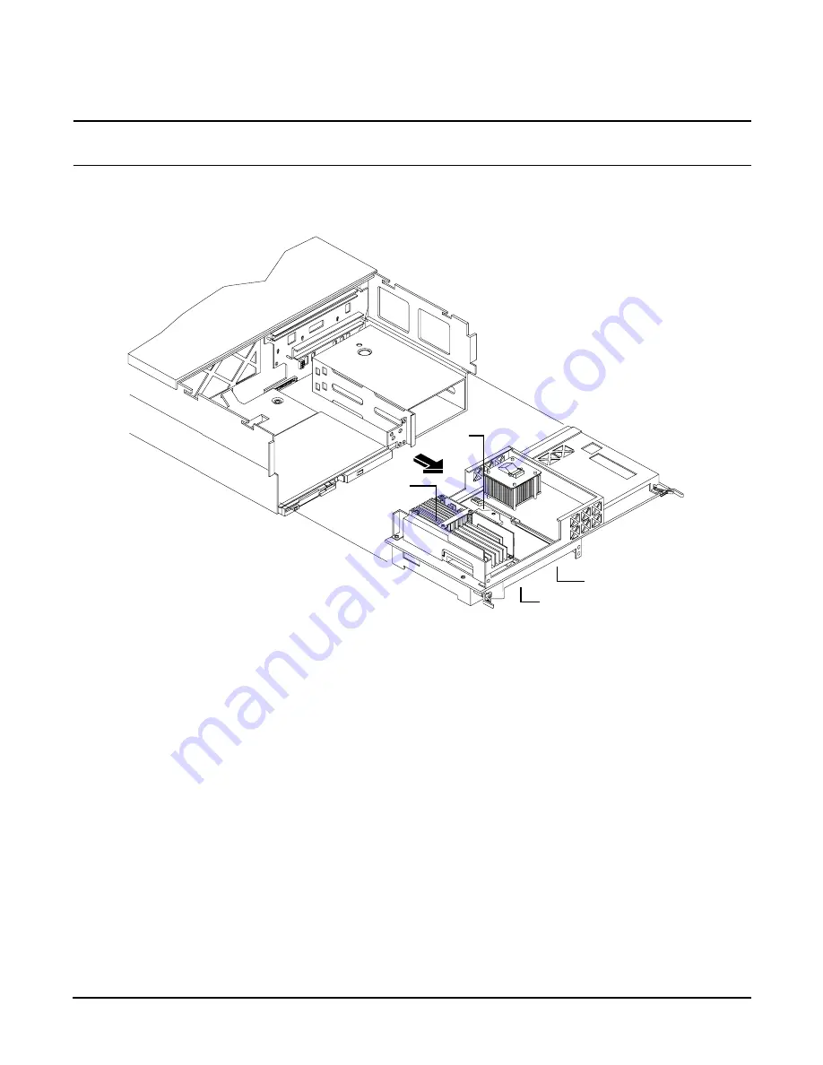
Figure 4-7
Removing the Processor Extender Board
Installing a Processor on the Extender Board
To install a processor on the extender board, perform the following steps:
Prior to installing a processor into your system, read the following instructions carefully and refer to Figure 4-11, Installing
Processor on Extender Board Example, for a complete understanding of this process.
Step 1.
If rack mounted, slide the HP Server out from the rack until it stops. See “Accessing a Rack Mounted Server” on
page 141.
Step 2.
Remove the front bezel. See “Front Bezel” on page 144.
Step 3.
Remove the front cover. See “Removing the Front Cover” on page 145.
Step 4.
Press the latch on each extraction lever located on each side of the processor extender board.
Step 5.
Pull out on the extraction levers to unplug the processor extender board from the socket located on the midplane
riser board and pull the extender board straight out, Figure 4-8.
CPU 1
CPU 0
CPU 3 (under)
CPU 2 (under)
Содержание Integrity rx4640
Страница 8: ...Contents 8 ...
Страница 14: ...Chapter 1 About This Document Where to Get Help 14 ...
Страница 28: ...Chapter 2 Controls Ports and Indicators Rear Panel 28 ...
Страница 86: ...Chapter 4 Installing Additional Components and Configuring Booting the Server 86 ...
Страница 120: ...Chapter 5 Utilities Management Processor Command Interface 120 ...
Страница 121: ...Chapter 5 Utilities Management Processor Command Interface 121 ...
Страница 122: ...Chapter 5 Utilities Management Processor Command Interface 122 ...
Страница 138: ...Chapter 6 Troubleshooting Troubleshooting Using Offline Support Tools 138 ...
Страница 139: ...Chapter 6 Troubleshooting Troubleshooting Using Offline Support Tools 139 ...
Страница 140: ...Chapter 6 Troubleshooting Troubleshooting Using Offline Support Tools 140 ...
Страница 190: ...Chapter 7 Removing and Replacing Components OLX Dividers 190 Figure 7 25 OLX Divider Latch CLOSED OPEN ...
Страница 197: ...Chapter 7 Removing and Replacing Components Hot Plug Disk Drives 197 Figure 7 29 Volume Filler Installation in Slot 2 ...
Страница 210: ...Chapter 7 Removing and Replacing Components DVD Drive 210 Step 3 Replace the front bezel ...
Страница 216: ...Chapter 7 Removing and Replacing Components Display Board 216 Figure 7 36 Display Board Removal and Replacement ...
Страница 221: ...Chapter 7 Removing and Replacing Components QuickFind Diagnostic Board 221 ...
Страница 222: ...Chapter 7 Removing and Replacing Components QuickFind Diagnostic Board 222 ...
Страница 226: ...Chapter 8 Parts Information Field Replaceable Parts FRU List 226 ...
Страница 229: ...Chapter 9 Specifications Dimensions and Weights 229 ...
Страница 230: ...Chapter 9 Specifications Dimensions and Weights 230 ...


