140
UDC 3300 Process Controller Product Manual
4/00
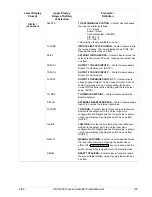
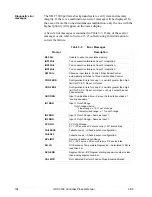
Lower Display
Prompt
Upper Display
Range of Setting
or Selection
Parameter
Definition
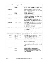
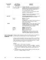
A2S2 VAL*
Value in engineering units
ALARM 2 SETPOINT 2 VALUE—This is the value at
which you want the alarm type chosen in prompt
A2S2TYPE to actuate.
The details are the same as A1S1 VAL.
*When the associated type is configured for Alarm on Totalizer Value, the Alarm SP value represents the four lowest digits for the
selected Totalizer Scale Factor. When the Totalizer value exceeds the Alarm SP, the alarm is activated. The range is 0 to 9999 x
Totalizer Scale Factor.
*When the associated type is configured for a HealthWatch Maintenance Timer, the Alarm SP represents number of hours.
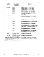
A1S1TYPE
NONE
INP 1
INP 2
INP 3
PV
DEV
OUTPUT
SHED
EV ON
EV OFF
MANUAL
REM SP
F SAFE
PVRATE
PV 2
DEV 2
OUT 2
MAN 2
RSP 2
F SAF2
PVRAT2
BREAK
BREAK2
TOTAL
TIMER1
TIMER2
TIMER3
COUNT1
COUNT2
COUNT3
ALARM 1 SETPOINT 1 TYPE—Select what you want
Setpoint 1 of Alarm 1 to represent. It can represent the
Process Variable, Deviation, Input 1, Input 2, Output, and
if you have a model with communications, you can
configure the controller to alarm on SHED. If you have
setpoint programming, you can alarm when a segment
goes ON or OFF.
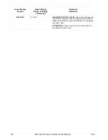
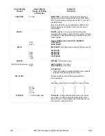
NO ALARM
INPUT 1
INPUT 2
INPUT 3
PROCESS VARIABLE (Loop 1)
DEVIATION (Loop 1)
OUTPUT (Loop 1) (NOTE 1)
SHED FROM COMMUNICATIONS (Both Loops)
EVENT ON (SP PROGRAMMING)
EVENT OFF (SP PROGRAMMING)
ALARM ON MANUAL MODE (Loop 1) (NOTE 2)
REMOTE SETPOINT
FAILSAFE
PV RATE OF CHANGE (Loop 1)
PROCESS VARIABLE (Loop 2)
DEVIATION (Loop 2)
OUTPUT (Loop 2) (NOTE 1)
ALARM ON MANUAL MODE (Loop 2) (NOTE 2)
REMOTE SETPOINT (Loop 2)
FAILSAFE (Loop 2)
PV RATE OF CHANGE (Loop 2)
LOOP BREAK (Loop 1) (NOTE 3)
LOOP BREAK (Loop 2) (NOTE 3)
ALARM ON TOTALIZER VALUE
HEALTHWATCH MAINTENANCE TIMER 1 VALUE
HEALTHWATCH MAINTENANCE TIMER 2 VALUE
HEALTHWATCH MAINTENANCE TIMER 3 VALUE
HEALTHWATCH MAINTENANCE COUNTER 1 VALUE
HEALTHWATCH MAINTENANCE COUNTER 2 VALUE
HEALTHWATCH MAINTENANCE COUNTER 3 VALUE
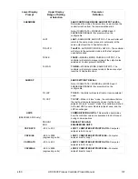
ATTENTION
NOTE 1. When the controller is configured for Three
Position Step Control, alarms set for Output will not
function.
NOTE 2. Not available if Timer is enabled because Alarm
1 is dedicated to Timer output.
NOTE 3. When enabled, the control output is checked for
minimum and maximum limits. When this occurs, a timer
begins and, if the output has not caused the PV to be
corrected by a pre-determined amount and time, the alarm
activates. For loop break alarms, the timer value may be
changed only for loops configured for On-Off control.
Содержание UDC3300
Страница 1: ...Sensing and Control UDC 3300 Universal Digital Controller Product Manual 51 52 25 55D 4 00 ...
Страница 12: ...xii UDC 3300 Controller Product Manual 4 00 ...
Страница 18: ...6 UDC 3300 Controller Product Manual 4 00 ...
Страница 90: ...78 UDC 3300 Process Controller Product Manual 4 00 ...
Страница 230: ...218 UDC 3300 Controller Product Manual 4 00 ...
Страница 254: ...242 UDC 3300 Controller Product Manual 4 00 ...
Страница 292: ...Index 280 UDC 3300 Controller Product Manual 4 00 ...
Страница 293: ......


