4/00
UDC 3300 Controller Product Manual
173
Functional overview
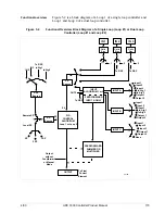
Figure 5-2 is a block diagram of a Loop 1 of a single loop controller and
Loop 1 and Loop 2 of a dual loop controller.
Figure 5-2
Functional Overview Block Diagram of a Single Loop (Loop #1) or Dual Loop
Controller (Loop #1 and Loop #2)
24180
IN 1
Ratio
Bias
•
•
•
IN 2
Ratio
Bias
•
•
•
1
2
PV
Source
IN 2
In Alg2
RSP
Source
Input 1
Input 2
Output 1
Output 2
INPUT A
INPUT B
INPUT C
INPUT
ALGORITHM 1 or 2
FEEDFORWARD
INPUT A ONLY
To RSP
SP
Source
SP
PV
Remote SP
Local SP
SP
2SP
3SP
To RSP
•
To RSP
PID
CONTROL
ALGORITHM
Loop 1 or Loop 2
FEEDFORWARD
SUMMER OR
MULTIPLIER
OUTPUT
Output
without
Feedforward
or Manual
Mode
To Final
Control
Element
None
OUT 2
In Alg1
IN 3
Ratio
Bias
•
•
•
3
•
To RSP
IN 3
Input 1
Input 2
In Alg 1
In Alg 2
Output 2
Output 1
Input 3
Input 1
Input 2
In Alg 1
In Alg 2
Output 2
Output 1
Input 3
Input 3
Содержание UDC3300
Страница 1: ...Sensing and Control UDC 3300 Universal Digital Controller Product Manual 51 52 25 55D 4 00 ...
Страница 12: ...xii UDC 3300 Controller Product Manual 4 00 ...
Страница 18: ...6 UDC 3300 Controller Product Manual 4 00 ...
Страница 90: ...78 UDC 3300 Process Controller Product Manual 4 00 ...
Страница 230: ...218 UDC 3300 Controller Product Manual 4 00 ...
Страница 254: ...242 UDC 3300 Controller Product Manual 4 00 ...
Страница 292: ...Index 280 UDC 3300 Controller Product Manual 4 00 ...
Страница 293: ......

