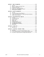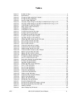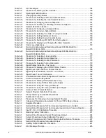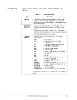
viii
UDC 3300 Controller Product Manual
4/00
Figures
Figure 1-1
Operator Interface Displays and Indicators......................................................................3
Figure 2-1
Model Number Interpretation ......................................................................................... 12
Figure 2-2
Dimensions .................................................................................................................... 13
Figure 2-3
Mounting Method ........................................................................................................... 14
Figure 2-4
Composite Wiring Diagram ............................................................................................ 18
Figure 2-5
Line Voltage Wiring ........................................................................................................ 19
Figure 2-6
Input #1/Input #2 Connections ....................................................................................... 20
Figure 2-7
Two HLAI Replace 2nd LLAI Connections..................................................................... 21
Figure 2-8
Electromechanical Relay Output—Model DC330X-EE-XXX.......................................... 22
Figure 2-9
Solid State Relay Output—Model DC330X-AA-XX........................................................ 23
Figure 2-10
10-amp Solid State Relay Output—Model DC330X-SS-XX........................................... 24
Figure 2-11
Open Collector Output—Model DC330X-TT-XXX ......................................................... 25
Figure 2-12
Current Output—Current /Time Duplex, Time/Current Duplex, Position
Proportional, or Three Position Step Control ................................................................. 26
Figure 2-13
Auxiliary Output and Three Relay Outputs..................................................................... 27
Figure 2-14
Position Proportional Output or Three Position Step—Models
DC330X-EE-XXX-X2, DC330X-AA-XXX-X2 .................................................................. 28
Figure 2-15
Auxiliary Output Connections—Models DC330X-XX-2XX, DC330X-XX-5XX................ 29
Figure 2-16
Digital Inputs Connections—Model DC330X-XX-XX3.................................................... 29
Figure 2-17
RS422/485/Modbus Communications Option Connections ........................................... 30
Figure 2-18
DMCS Communications Option Connections ................................................................ 31
Figure 2-19
Transmitter Power for 4-20 mA 2-wire Transmitter Using Open Collector
Alarm 2 Output—Model DC330X-XT-XXX..................................................................... 32
Figure 2-20
Transmitter Power for 4-20 mA 2-wire Transmitter Using Auxiliary Output—
Model DC330X-XX-2XX or DC330X-XX-5XX ................................................................ 33
Figure 3-1
Overview of UDC 3300 Prompt Hierarchy ..................................................................... 36
Figure 4-1
Example of Mass Flow Compensation using Multiplier/Divider Algorithm.................... 102
Figure 4-2
Example of Eight Segment Characterizer .................................................................... 106
Figure 5-1
Operator Interface ........................................................................................................ 151
Figure 5-2
Functional Overview Block Diagram of a Single Loop (Loop #1) or Dual
Loop Controller (Loop #1 and Loop #2) ....................................................................... 173
Figure 5-3
Functional Overview Block Diagram of Internal Cascade of a 2-loop Controller.......... 174
Figure 5-4
Hi/Lo Override Selector................................................................................................ 175
Figure 5-5
Auto/Manual Station and Backup Control Feature ....................................................... 190
Figure 5-6
Carbon Potential Control.............................................................................................. 203
Figure 6-1
Ramp/Soak Profile Example ........................................................................................ 209
Figure 6-2
Program Record Sheet ................................................................................................ 210
Figure 7-1
Inputs #1, #2, and #3 Wiring Terminals ....................................................................... 221
Figure 7-2
Wiring Connections for Thermocouple Inputs Using an Ice Bath................................. 223
Figure 7-3
Wiring Connections for Thermocouple Inputs Using a Precision Resistor ................... 224
Figure 7-4
Wiring Connections for RTD ........................................................................................ 225
Figure 7-5
Wiring Connections for Radiamatic, Millivolts, or Volts (except 0 to 10 Volts) ............. 226
Figure 7-6
Wiring Connections for 0 to 10 Volt Inputs ................................................................... 227
Figure 7-7
Wiring Connections for 4 to 20 mA inputs .................................................................... 228
Figure 8-1
Wiring Connections for Calibrating Current Proportional Output ................................. 234
Figure 8-2
Wiring Connections for Calibrating Auxiliary Output .................................................... 240
Figure 9-1
Chassis Removal ......................................................................................................... 262
Figure 9-2
Display/Keyboard Replacement ................................................................................... 263
Figure 9-3
Removing the Printed Wiring Boards ........................................................................... 264
Figure 9-4
Printed Wiring Board Identification ............................................................................... 265
Figure 10-1
UDC 3300 Exploded View............................................................................................ 271
Содержание UDC3300
Страница 1: ...Sensing and Control UDC 3300 Universal Digital Controller Product Manual 51 52 25 55D 4 00 ...
Страница 12: ...xii UDC 3300 Controller Product Manual 4 00 ...
Страница 18: ...6 UDC 3300 Controller Product Manual 4 00 ...
Страница 90: ...78 UDC 3300 Process Controller Product Manual 4 00 ...
Страница 230: ...218 UDC 3300 Controller Product Manual 4 00 ...
Страница 254: ...242 UDC 3300 Controller Product Manual 4 00 ...
Страница 292: ...Index 280 UDC 3300 Controller Product Manual 4 00 ...
Страница 293: ......


