background image

Honeywell

 • 61

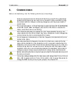
C

OMMISSIONING

6.3

Installation in IT system

If your supply network is an IT (impedance-grounded) system but your drive is EMC-protected according 
to class C2 you need to modify the EMC protection of the drive to EMC-level C4. This is done by removing 
the built-in EMC jumpers with a simple procedure described below.

NOTE: 

Honeywell SmartDrive HVAC 230V products with letter ‘T’ in the end of the product 

code (HVAC230-xxx-xxT) are as standard configured to IT-networks and do not need any mod-
ifications.

6.3.1

Frames MR4 to MR6

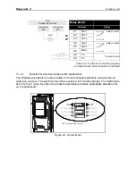
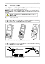
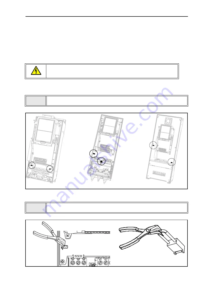
Figure 51. Locations of the EMC-jumpers in frames MR4 to MR6

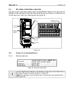
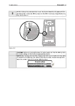
Figure 52. Removing the jumper, MR5 as example

Warning! Do not perform any modifications on the drive when it is con-
nected to mains.

1

Remove the main cover of the drive (see pages 28 and 28) and locate the jumpers 
connecting the built-in RFI-filters to ground. See Figure 51.

2

Disconnect the RFI-filters from ground by removing the EMC-jumpers using long-
nose pliers or similar. See Figure 52.

MR4

MR6

MR5

Содержание SmartDrive HVAC

Страница 1: ...Honeywell Installation manual SmartDrive HVAC Variable Frequency Drive for Heating Ventilation and Air conditioning applications ...

Страница 2: ... on cabling 21 4 1 1 Cable dimensioning and selection 21 4 2 Cable installation 26 4 2 1 Frames MR4 to MR7 27 4 2 2 Frames MR8 and MR9 33 4 3 Installation in corner grounded network 43 5 Control unit 44 5 1 Control unit cabling 45 5 1 1 Control cable sizing 45 5 1 2 Control terminals and DIP switches 46 5 2 I O cabling and fieldbus connection 49 5 2 1 Prepare for use through Ethernet 49 5 2 2 Prep...

Страница 3: ...5 7 Technical data 67 7 1 Drive power ratings 67 7 1 1 Mains voltage 208 240 V 67 7 1 2 Mains voltage 380 480 V 68 7 1 3 Definitions of overloadability 69 7 2 Technical data 70 7 2 1 Technical information on control connections 73 ...

Страница 4: ... out if no keypad is attached see the indicators on the cover Wait 5 more minutes before doing any work on the connections of the drive Do not open the cover before this time has expired After expiration of this time use a measur ing equipment to absolutely ensure that no voltage is present Always ensure absence of voltage before starting any electrical work The control I O terminals are isolated ...

Страница 5: ... machine manufacturer is responsible for providing the machine with a supply disconnecting device EN 60204 1 Only spare parts delivered by Honeywell can be used At power up power brake or fault reset the motor will start immediately if the start signal is active unless the pulse control for Start Stop logic has been selected Futhermore the I O functionalities including start inputs may change if p...

Страница 6: ...h capacitive currents present in the drive fault current protective switches may not function properly 1 4 EMC levels SmartDrive HVAC inverters are divided into three classes according to the level of electromag netic disturbances emitted the requirements of a power system network and the installation environment see below The EMC class of each product is defined in the type designation code Categ...

Страница 7: ...ied to the requirements of the T class This class is very typical requirement also in installations in ships Also the 230V SmartDrive HVAC products can be ordered as ready configured to this class by adding a T to the end of standard product code HVAC230 xxx xxT Environments in product standard EN 61800 3 2004 First environment Environment that includes domestic premises It also includes establish...

Страница 8: ...delivery by comparing your order data to the drive information found on the package label If the delivery does not correspond to your order contact the supplier immediately See chapter 2 3 Date code batch ID yyww Product type Product serial number Electrical data and enclosure class ...

Страница 9: ...ced commissioning keypad instead of standard text keypad Available only with 400V prod ucts HVAC400 xxx xxA S Models with integrated load switch Available only with IP54 400V products HVAC400 xxx 54S T Configured ready for the require ments of IT network and including the advanced commissioning keypad instead of standard text keypad Available only with 230V prod ucts HVAC230 xxx xxT HVAC 400 1P1 5...

Страница 10: ...quality checks at the factory before they are delivered to the customer However after unpacking the product check that no signs of trans port damages are to be found on the product and that the delivery is complete Frame Nominal power 400V 3 series Nominal power 230V 3 series Weight kg MR4 1 1 5 5 kW 0 55 3 0 kW 6 0 MR5 7 5 15 0 kW 4 0 7 5 kW 10 0 MR6 18 5 30 0 kW 11 0 15 0 kW 20 0 MR7 37 0 55 0 k...

Страница 11: ...Honeywell 9 RECEIPT OF DELIVERY Should the drive have been damaged during the shipping please contact primarily the cargo insurance company or the carrier ...

Страница 12: ...3 Clamping power cables Grounding clamp 2 Power cable grounding Product modified label 1 Information about modifications IP21 Cable grommet 3 Cable run through sealing IP54 Cable grommet 6 Cable run through sealing Item Quantity Purpose M4x16 screw 13 Screws for power cable clamps 6 control cable clamps 3 grounding clamps 4 M4x8 screw 1 Screw for optional grounding M5x12 screw 1 Screw for drive ex...

Страница 13: ...e grounding Product modified label 1 Information about modifications Cable grommet hole diameter 33 0 mm 1 Cable run through sealing Cable grommet hole diameter 40 3 mm 2 Cable run through sealing IP54 Cable grommet hole diameter 25 3 mm 3 Cable run through sealing Item Quantity Purpose M5x30 slotted nut 6 Nuts for power cable clamps M4x16 screw 3 Screws for control cable clamps M6x12 screw 1 Scre...

Страница 14: ...ole diameter 25 3 mm 4 Control cable run through sealing IP00 Touch protection shield 1 Avoiding contact with live parts IP00 M4x8 screw 2 Fixing the touch protection shield Item Quantity Purpose M4x16 screw 3 Screws for control cable clamps Control cable grounding lamella 3 Control cable grounding Cable lugs KP40 5 Clamping power cables Cable insulator 10 Avoiding contact between cables Cable gro...

Страница 15: ...silver Product modified sticker The purpose of the sticker is to notify the service personnel about the modifications made in the drive Attach the sticker on the side of the drive to avoid losing it Should the drive be later modified mark the change on the sticker Figure 3 Product modified sticker Product modified Date Date Date ...

Страница 16: ... position on the wall or on the back plane of a cubicle Ensure that the mounting plane is relatively even The drive shall be fixed with four screws or bolts depending on the unit size 3 1 Dimensions Figure 4 SmartDrive dimensions MR4 128 100 Ø7 Ø13 100 190 IP21 Ø25 IP54 Ø25 ...

Страница 17: ...e 5 SmartDrive dimensions MR5 Figure 6 SmartDrive dimensions MR6 Optional mounting holes for NX replacement 214 144 115 Ø7 Ø14 Ø7 100 115 Ø7 100 IP21 Ø33 Ø33 Ø25 IP54 Ø25 195 148 Ø 15 5 Ø9 Ø9 148 229 IP21 Ø40 Ø33 Ø40 IP54 Ø25 Ø25 ...

Страница 18: ...eywell 16 3 Figure 7 SmartDrive dimensions MR7 Figure 8 SmartDrive dimensions MR8 IP21 and IP54 259 Ø20 237 190 Ø9 Ø16 Ø51 IP21 IP54 Ø25 Ø50 Ø25 3 x 38 Ø60 62 5 164 290 Ø22 343 Ø11 Ø9 216 672 694 956 235 217 Ø9 0 9 ...

Страница 19: ...Honeywell 17 MOUNTING Figure 9 SmartDrive dimensions MR9 IP21 and IP54 84 3 x 42 126 Ø25 318 166 77 4 x 81 5 326 Ø59 ...

Страница 20: ...e cooling air does not exceed the maximum ambient tem perature of the converter Table 11 Min clearances around drive Figure 10 Installation space A clearance around the freq converter see also B B distance from one drive to another or distance to cabinet wall C free space above the drive D free space underneath the drive Min clearance mm Type A Min clearances A and B for drives with IP54 enclosure...

Страница 21: ...the lower unit must be directed away from the air in take of the upper unit by means of e g a piece of met al plate fixed to cabinet wall between the drives as shown in Figure 11 Figure 11 Installation space when drives are mounted on top of each other Table 12 Required cooling air Type Cooling air required m3 h MR4 45 MR5 75 MR6 190 MR7 185 MR8 335 MR9 621 C D FRONT SIDE ...

Страница 22: ...andards 1 Power cable intended for fixed installation and the specific mains voltage Shielded cable not required MCMK or similar recommended 2 Symmetrical power cable equipped with concentric protection wire and intended for the specific mains voltage MCMK or similar recommended See Figure 13 3 Symmetrical power cable equipped with compact low impedance shield and intended for the specific mains v...

Страница 23: ...To meet the UL Underwriters Laboratories regulations use a UL approved copper cable with a minimum heat resistance of 60 75 C Use Class 1 wire only The units are suitable for use on a circuit capable of delivering not more than 100 000 rms sym metrical amperes 600V maximum 4 1 1 Cable dimensioning and selection Table 14 shows the minimum dimensions of the Cu Al cables and the corresponding fuse si...

Страница 24: ...th concentric copper shield Max number of parallel cables is 9 When using cables in parallel NOTE HOWEVER that the requirements of both the cross sectional area and the max number of cables must be observed For important information on the requirements of the earthing conductor see chapter Earthing and earth fault protection of the standard For the correction factors for each temperature see Inter...

Страница 25: ...Max number of parallel cables is 9 When using cables in parallel NOTE HOWEVER that the requirements of both the cross sectional area and the max number of cables must be observed For important information on the requirements of the earthing conductor see chapter Earthing and earth fault protection of the standard For the correction factors for each temperature see International Standard IEC60364 5...

Страница 26: ... 9 When using cables in parallel NOTE HOWEVER that the requirements of both the cross sectional area and the max number of cables must be observed For important information on the requirements of the earthing conductor see standard Underwriters Laboratories UL508C For the correction factors for each temperature see the instructions of standard Underwriters Laboratories UL508C Frame Type IL A Fuse ...

Страница 27: ... cable surface 70 C Use only cables with concentric copper shield Max number of parallel cables is 9 When using cables in parallel NOTE HOWEVER that the requirements of both the cross sectional area and the max number of cables must be observed For important information on the requirements of the earthing conductor see standard Underwriters Laboratories UL508C For the correction factors for each t...

Страница 28: ...te the minimum distances between the motor cables and other cables given in table below The given distances also apply between the motor cables and signal cables of other systems The maximum lengths of motor cables shielded are 100 m MR4 150 m MR5 and MR6 and 200 m MR7 to MR9 The motor cables should cross other cables at an angle of 90 degrees If cable insulation checks are needed see chapter Cabl...

Страница 29: ...pping lengths mm 1 Strip the motor and mains cables as advised below Frame A1 B1 C1 D1 C2 D2 E MR4 15 35 10 20 7 35 Leave as short as pos sible MR5 20 40 10 30 10 40 MR6 20 90 15 60 15 60 MR7 20 80 20 80 20 80 2 Open the cover of the drive D1 B1 C1 A1 D2 C2 Earth conductor MAINS MOTOR Earth conductor E ...

Страница 30: ...POWER CABLING Honeywell 28 4 Figure 15 Figure 16 3 Remove the screws of the cable protection plate Do not open the cover of the power unit M4x55 M4x8 ...

Страница 31: ... cables through Should the grommets fold in while inserting the cable just draw the cable back a bit to straighten the grommets up Do not cut the grommet openings wider than what is necessary for the cables you are using IMPORTANT NOTE FOR IP54 INSTALLATION To meet the requirements of the enclosure class IP54 the connection between the grommet and the cable must be tight Therefore lead the first b...

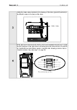
Страница 32: ...CABLING Honeywell 30 4 Figure 18 Figure 19 6 Detach the cable clamps and the grounding clamps Figure 19 and place the cable entry plate with the cables in the groove on the drive frame Figure 20 M4x16 2 2 Nm ...

Страница 33: ... degree con nection with the cable clamp 1 Connect the phase conductors of the supply brake and motor cables into their respective terminals 2 Form the rest of the cable shield of all three cables into pigtails and make a grounding connection with a clamp as shown in Figure 21 3 Make the pigtails just long enough to reach and be fixed to the terminal not longer L1L2L3 R R U V W 1 2 3 3 ...

Страница 34: ...6 4 5 5 3 1 5 13 3 2 0 17 7 MR5 230 4P0 230 7P5 400 7P5 400 15P 1 2 1 5 10 6 13 3 1 5 13 3 2 0 17 7 MR6 230 11P 230 15P 400 18P 400 30P 10 88 5 1 5 13 3 2 0 17 7 MR7 230 18P 230 30P 400 37P 400 55P 8 15 Cable clamping e g Ouneva Pressure Terminal Connector 70 8 132 8 1 5 13 3 8 15 70 8 132 8 8 Check the connection of the earth cable to the motor and the drive terminals marked with NOTE Two protect...

Страница 35: ...r components 4 2 2 Frames MR8 and MR9 Figure 24 Stripping of cables 9 Re mount the cable protection plate Figure 23 and the cover of the drive 1 Strip the motor and mains cables as advised below D1 B1 C1 A1 D2 C2 Earth conductor MAINS MOTOR Earth conductor E ...

Страница 36: ...e 26 Removing cable cover and cable fitting plate MR8 Frame A1 B1 C1 D1 C2 D2 E MR8 40 180 25 300 25 300 Leave as short as possible MR9 40 180 25 300 25 300 2 MR9 only Remove the main cover of the drive 3 Remove the cable cover 1 and the cable fitting plate 2 M4 x 10 M4x8 1 M4 x 8 2 ...

Страница 37: ...Honeywell 35 POWER CABLING Figure 27 Removing cable cover and cable fitting plate MR9 Figure 28 4 MR9 only Loosen the screws and remove the sealing plate M4 x 8 1 2 M5 x 10 ...

Страница 38: ...POWER CABLING Honeywell 36 4 Figure 29 Figure 30 5 Remove the EMC shield plate 6 Locate the terminals OBSERVE the exceptional placement of motor cable ter minals in MR8 MR9 MR8 M5 M4x8 ...

Страница 39: ...or the cables you are using 8 Place the grommet with the cable so that the frame end plate fits in the groove on the grommet see Figure 32 To meet the requirements of the enclosure class IP54 the connection between the grommet and the cable must be tight Therefore lead the first bit of the cable out of the grommet straight before letting it bend If this is not possible the tight ness of the connec...

Страница 40: ...hown in Figure 24 Connect the phase conductors of the supply brake and motor cables into their respective terminals a Form the rest of the cable shield of all cables into pigtails and make a grounding connection as shown in Figure 34 b using the clamp from the Accessories bag NOTE If you use several cables on one connector observe the position of cable lugs on top of each other See Figure 35 below...

Страница 41: ...tor terminals Tightening torque Nm lb in EMC grounding clamps Tightening torque Nm lb in Grounding terminals Nm lb in Nm lb in Nm lb in MR8 230 37P 230 55P 400 75P 400 110 20 40 Cable clamping e g Ouneva Pressure Terminal Connector 177 354 1 5 13 3 20 177 MR9 230 75P 230 90P 400 132 400 160 20 40 177 354 1 5 13 3 20 177 L1 L2 L3 DC DC R R b a MR8 U W V L1 L2 L3 DC DC R R U V W MR9 a b a b Cable lu...

Страница 42: ...eld of all three cables in order to make a 360 degree connection with the cable clamp 12 Remount now first the EMC shield plate see Figure 30 and then the sealing plate for MR9 see Figure 29 13 Re attach then the cable fitting plate and then the cable cover M4x8 M4x8 ...

Страница 43: ...of the earth cable to the motor and the drive terminals marked with NOTE Two protective conductors are required according to standard EN61800 5 1 See chapter Earthing and earth fault protection Connect the protective conductor using a cable shoe and an M8 screw included in the Accessories bag on either of the screw connectors as advised in Figure 39 M4x10 ...

Страница 44: ...POWER CABLING Honeywell 42 4 Figure 39 ...

Страница 45: ...0 A at 380 480 V supply and from 75 A to 310 A at 208 240 V supply In these circumstances the EMC protection class must be changed to level C4 following the instructions in chapter 6 3 of this manual Corner grounding is not allowed for the drive types with rating from 3 4 A to 61 A at 380 480 V supply and 3 7 A to 62 A with 208 240 V supply ...

Страница 46: ...t of the control I O and the relay terminals the general wiring diagram and the control signal descriptions The control board can be powered externally 24VDC 100mA 10 by connecting the ex ternal power source to terminal 30 see page 46 This voltage is sufficient for parameter set ting and for keeping the control unit active Note however that the measurements of the main circuit e g DC link voltage ...

Страница 47: ...ble sizing The control cables shall be at least 0 5 mm2 screened multicore cables see Table 13 The maximum terminal wire size is 2 5 mm2 for the relay and other terminals Find the tightening torques of the control and relay board terminals in Table 22 below Table 22 Control cable tightening torques Terminal screw Tightening torque Nm lb in All I O and relay terminals screw M3 0 5 4 5 28 29 12 13 1...

Страница 48: ...utput 2 AI1 Analogue input voltage or current 3 AI1 Analogue input com mon current 4 AI2 Analogue input voltage or current 5 AI2 Analogue input com mon current 6 24Vout 24V aux voltage 7 GND I O ground 8 DI1 Digital input 1 9 DI2 Digital input 2 10 DI3 Digital input 3 11 CM Common for DI1 DI6 Digital inputs can be disconnected from ground see chapter 5 1 2 2 12 24Vout 24V aux voltage 13 GND I O gr...

Страница 49: ...ave three positions left middle and right The middle posi tion is for Test mode See figure to locate the switches and make appropriate selections for your requirements Figure 42 Dip switches Relay board Terminal Signal 21 RO1 1 Relay output 1 22 RO1 2 23 RO1 3 24 RO2 1 Relay output 2 25 RO2 2 26 RO2 3 28 TI1 Thermistor input 29 TI1 From Standard I O board From term 13 From term 12 RUN RS485 AO1 AI...

Страница 50: ...rminals 8 10 and 14 16 on the standard I O board can be isolated from ground by removing a jumper on the control board See Figure 43 Lift the plastic lid to expose the jumper and apply long nose pliers or similar to remove it Figure 43 Remove this jumper to isolate the digital inputs from ground ...

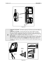
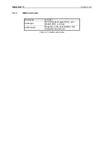
Страница 51: ...ata Table 25 Ethernet cable data Connector Shielded RJ45 connector NOTE Max length of the connector 40mm Cable type CAT5e STP Cable length Max 100m 1 Connect the Ethernet cable see specification on page 49 to its terminal and run the cable through the conduit as shown in Figure 45 NOTE Pay attention that the length of the connector does not exceed 40 mm See Figure 50 Ethernet connector Ethernet ca...

Страница 52: ...ck a bit to straighten the grommets up Do not cut the grommet openings wider than what is necessary for the cables you are using IMPORTANT To meet the requirements of the enclosure class IP54 the connec tion between the grommet and the cable must be tight Therefore lead the first bit of the cable out of the grommet straight before letting it bend If this is not possible the tightness of the connec...

Страница 53: ...able data Table 26 RS485 cable data 3 Remount the drive cover NOTE When planning the cable runs remember to keep the distance between the Ethernet cable and the motor cable at a minimum of 30 cm Connector 2 5 mm2 Cable type STP Shielded Twisted Pair type Belden 9841 or similar Cable length Depends on the used fieldbus See respective bus manual Ethernet cable IP21 IP54 ...

Страница 54: ...inals See picture below Also strip the cable now at such a distance from the terminal that you can fix it to the frame with the grounding clamp Strip the cable at a maximum length of 15 mm Do not strip the aluminum cable shield 2 Then connect the cable to its appropriate terminals on the drive drive standard terminal block terminals A and B A negative B positive See Figure 48 10 5 B 20 A 11 8 9 10...

Страница 55: ... device on the bus the bus termination must be set Locate the DIP switches to the right of the control keypad of the drive and turn the switch for the RS485 bus termination resistor to position ON Biasing is built in the ter mination resistor See also step 7 on page 54 Cable clamp RS485 AO1 AI2 AI1 OFF ON Current Voltage Current Voltage Current Voltage Bus termination resistor ...

Страница 56: ...ble runs remem ber to keep the distance between the fieldbus cable and the motor cable at a minimum of 30 cm 7 The bus termination must be set for the first and the last device of the fieldbus line See picture below See also step 4 on page 53 We recommend that the first device on the bus and thus terminated was the Master device Fieldbus cables BACnet MS TP Bus termination Termination activated Te...

Страница 57: ... CONTROL UNIT 5 2 3 RS485 cable data Table 27 RS485 cable data Connector 2 5 mm2 Cable type STP Shielded Twisted Pair type Belden 9841 or similar Cable length Depends on the used fieldbus See respective bus manual ...

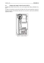
Страница 58: ... the Real Time Clock RTC requires that a battery is installed in the drive The place for the battery can be found in all frames left to the control keypad see Figure 49 Detailed information on the functions of the Real Time Clock RTC can be found in the HVAC Application Manual Figure 49 Optional battery ...

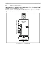
Страница 59: ...o ground See Figure 50 The digital inputs are galvanically isolated from the I O ground The relay outputs are addition ally double isolated from each other at 300VAC EN 50178 Figure 50 Galvanic isolation barriers CONTROL UNIT 10Vref GND 24V GND AI1 AI1 AI2 AI2 DI1 DI6 CM AO1 AO1 24Vin RS485 RO1 1 RO1 2 RO1 3 RO2 1 RO2 2 RO2 3 TI1 TI1 POWER UNIT L1 L2 L3 DC DC R R U V W ...

Страница 60: ...ive is disconnected from mains Do not make any connections to or from the frequency converter when it is con nected to the mains After disconnecting the frequency converter from the mains wait until the fan stops and the indicators on the keypad go out if no keypad is attached see the indicators on the cover Wait 5 more minutes before doing any work on the con nections of the drive Do not open the...

Страница 61: ...up Wizard see the Application Manual 6 2 Running the motor MOTOR RUN CHECK LIST 6 2 1 Cable and motor insulation checks 1 Motor cable insulation checks Disconnect the motor cable from terminals U V and W of the drive and from the motor Measure the insulation resistance of the motor cable between each phase conductor as well as between each phase conductor and the protective ground conductor The in...

Страница 62: ...ing connections in the motor connection box Measure the insulation resistance of each motor winding The measurement voltage must equal at least the motor nominal voltage but not exceed 1000 V The insulation resistance must be 1M at ambient temperature of 20 C Always follow the instructions of the motor manufacturer ...

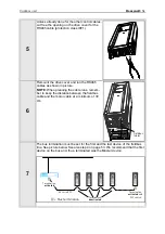
Страница 63: ... of the product code HVAC230 xxx xxT are as standard configured to IT networks and do not need any mod ifications 6 3 1 Frames MR4 to MR6 Figure 51 Locations of the EMC jumpers in frames MR4 to MR6 Figure 52 Removing the jumper MR5 as example Warning Do not perform any modifications on the drive when it is con nected to mains 1 Remove the main cover of the drive see pages 28 and 28 and locate the ...

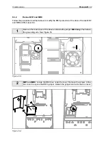
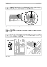
Страница 64: ...e drive of frames MR7 and MR8 to EMC level C4 Figure 53 Figure 54 1 Remove the main cover of the drive and locate the jumper MR8 only Push down the grounding arm See Figure 53 2 MR7 and MR8 Locate the EMC box under the cover Remove the screws of the box cover to expose the EMC jumper Detach the jumper and re fix the box cover ...

Страница 65: ...ve of frame MR9 to EMC level C4 Figure 56 3 MR7 only locate the DC grounding busbar between connectors R and U and detach the busbar from the frame by undoing the M4 screw 1 Find the Molex connector in the accessories bag Remove the main cover of the drive and locate the place for the connector next to the fan Push the Molex con nector in its place See Figure 56 Molex connector ...

Страница 66: ...ove it CAUTION Before connecting the drive to mains make sure that the EMC protec tion class settings of the drive are appropriately made NOTE After having performed the change write EMC level modified on the stick er included in the delivery see below and note the date Unless already done attach the sticker close to the name plate the drive Product modified Date Date Date EMC level modified C1 C4...

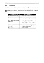
Страница 67: ...ming of capacitors is not neces sary Maintenance interval Maintenance action Regularly and according to general maintenance interval Check tightening torques of terminals Check filters 6 24 months depending on environment Check input and output terminals and control I O terminals Check operation of cooling fan Check for corrosion on terminals bus bars and other surfaces Check door filters in case ...

Страница 68: ...COMMISSIONING Honeywell 66 6 ...

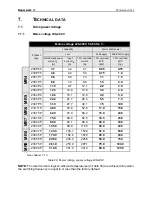
Страница 69: ... current A 10 overload 40 C kW 10 overload 40 C hp MR4 230 P55 3 7 3 2 4 1 0 55 0 75 230 P75 4 8 4 2 5 3 0 75 1 0 230 1P1 6 6 6 0 7 3 1 1 1 5 230 1P5 8 0 7 2 8 8 1 5 2 0 230 2P2 11 0 9 7 12 1 2 2 3 0 230 3P0 12 5 10 9 13 8 3 0 4 0 MR5 230 4P0 18 0 16 1 19 8 4 0 5 0 230 5P5 24 2 21 7 26 4 5 5 7 5 230 7P5 31 0 27 7 34 1 7 5 10 0 MR6 230 11P 48 0 43 8 52 8 11 0 15 0 230 15P 62 0 57 0 68 2 15 0 20 0 M...

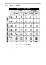
Страница 70: ...ad 40 C HP MR4 400 1P1 3 4 3 4 3 7 1 1 1 5 400 1P5 4 8 4 6 5 3 1 5 2 0 400 2P2 5 6 5 4 6 2 2 2 3 0 400 3P0 8 0 8 1 8 8 3 0 5 0 400 4P0 9 6 9 3 10 6 4 0 5 0 400 5P5 12 0 11 3 13 2 5 5 7 5 MR5 400 7P5 16 0 15 4 17 6 7 5 10 400 11P 23 0 21 3 25 3 11 0 15 0 400 15P 31 0 28 4 34 1 15 0 20 0 MR6 400 18P 38 0 36 7 41 8 18 5 25 0 400 22P 46 0 43 6 50 6 22 0 30 0 400 30P 61 0 58 2 67 1 30 0 40 0 MR7 400 37...

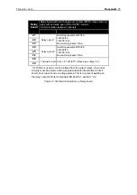
Страница 71: ...ration at rated output current IL the converter is fed with 110 IL for 1 min followed by a period of IL Example If the duty cycle requires 110 rated current IL for 1 min in every 10 min the remaining 9 min must be at rated current or less Figure 58 Low overload IL IL 110 1 min 9 min IL 110 Current Time ...

Страница 72: ...frequency 0 320 Hz standard Frequency resolution 0 01 Hz Control characteristics Switching frequency see parameter M3 1 2 1 1 5 10 kHz Defaults MR4 6 6 kHz except 230 3P0 230 7P5 230 15P 400 5P5 400 15P and 400 30P 4 kHz MR7 4 kHz MR8 9 3 kHz Automatic adjustment of switching fre quency by overtemperature ride through function in case of overload e g short time ambient temperature increase Frequen...

Страница 73: ... O signals Up to 2 000m Allowed up to 240V 2 000m 4 500m Allowed up to 120V Corner grounding up to 2 000m only Ambient conditions cont Vibration EN61800 5 1 EN60068 2 6 5 150 Hz Displacement amplitude 1 mm peak at 5 15 8 Hz MR4 MR9 Max acceleration amplitude 1 G at 15 8 150 Hz MR4 MR9 Shock EN61800 5 1 EN60068 2 27 UPS Drop Test for applicable UPS weights Storage and shipping max 15 G 11 ms in pac...

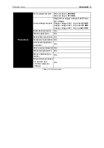
Страница 74: ...pply voltage 240 V Trip limit 211 VDC Supply voltage 400 V Trip limit 351 VDC Supply voltage 480 V Trip limit 421 VDC Earth fault protection Yes Mains supervision Yes Motor phase supervision Yes Overcurrent protection Yes Unit overtemperature protection Yes Motor overload protection Yes Motor stall protection Yes Motor underload pro tection Yes Short circuit protection of 24VDC and 10VDC reference...

Страница 75: ... unit Short circuit protected 7 I O ground Ground for reference and controls connected internally to frame earth through 1M 8 Digital input 1 Positive or negative logic Ri min 5k 0 5VDC 0 15 30VDC 1 9 Digital input 2 10 Digital input 3 11 Common A for DIN1 DIN6 Digital inputs can be disconnected from ground see chapter 5 1 2 2 12 24VDC aux voltage 24VDC 10 max volt ripple 100mVrms max 250mA Dimens...

Страница 76: ...s control voltage from the output relays the control circuitry must be powered with a separate isolation transformer to limit short circuit current and ovrvoltage spikes This is to prevent welding on the relay contacts Refer to standard EN 60204 1 section 7 2 9 Switching capacity24VDC 8A 250VAC 8A 125VDC 0 4A Min switching load5V 10mA 22 23 24 Relay output 2 Switching capacity24VDC 8A 250VAC 8A 12...

Страница 77: ...products visit us online at http ecc emea honeywell com Automation and Control Solutions Honeywell GmbH Böblinger Str 17 71101 Schönaich Germany Telephone 49 7031 637 01 Telefax 49 7073 637 493 www ecc emea honeywell com EN1B 0489GE51 R1210 December 2010 2010 Honeywell International Inc DPD00487D ...

Отзывы: