C
ONTROL
UNIT
Honeywell
• 44
5
5.
C
ONTROL
UNIT
The control unit of the drive consists of the control board and additional boards (option boards)
connected to the slot connectors of the control board.
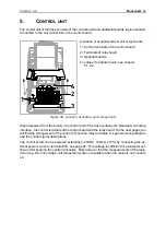
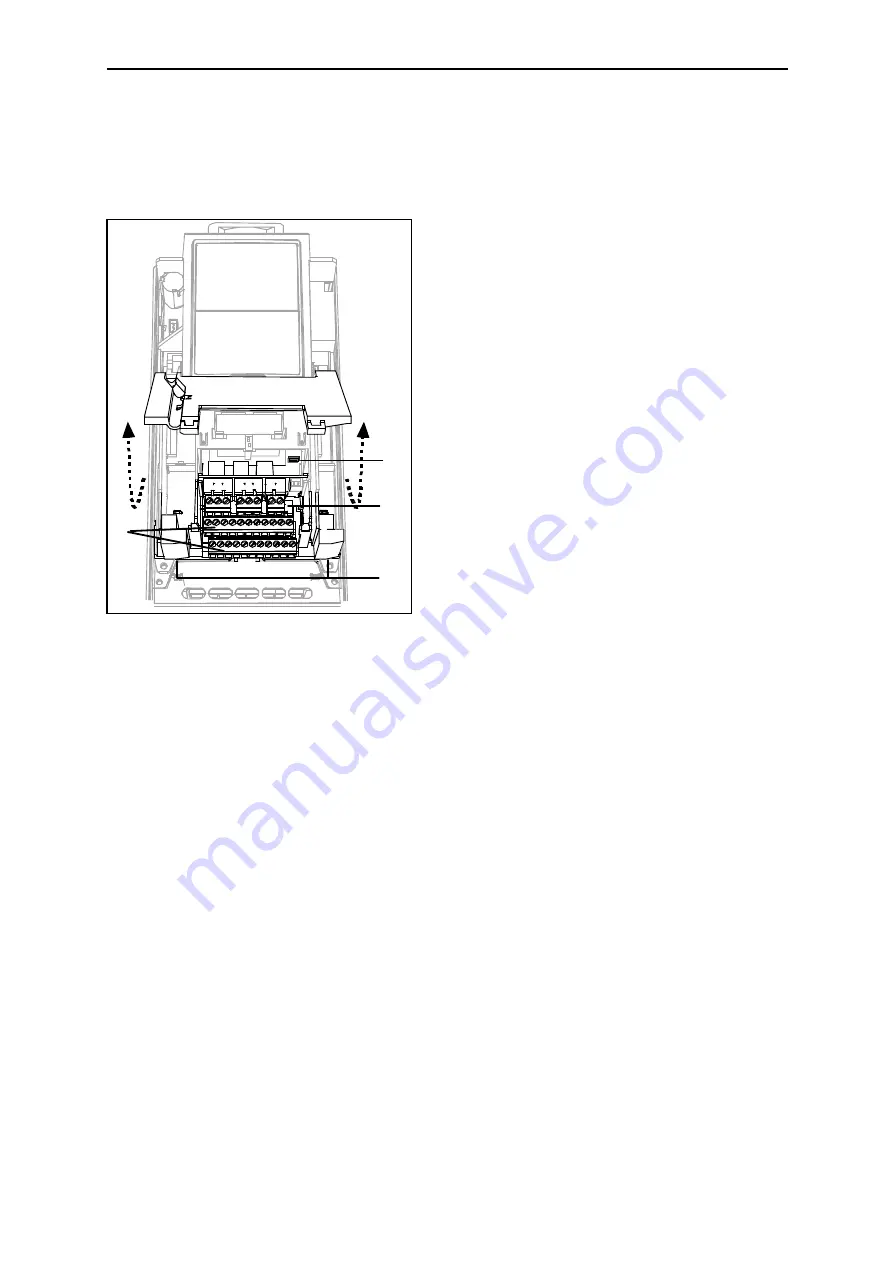
Figure 40. Location of control unit components
When delivered from the factory, the control unit of the drive contains the standard controlling
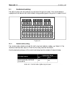
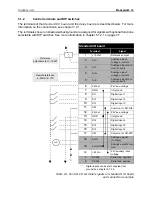
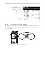
interface - the control terminals of the control board and the relay board. On the next pages you
will find the arrangement of the control I/O and the relay terminals, the general wiring diagram
and the control signal descriptions.
The control board can be powered externally (+24VDC, 100mA, ±10%) by connecting the ex-
ternal power source to terminal #30, see page 46. This voltage is sufficient for parameter set-
ting and for keeping the control unit active. Note however that the measurements of the main
circuit (e.g. DC-link voltage, unit temperature) are not available when the mains is not connect-
ed.
1
2
3
4
Locations of essential control unit components:
1 = Control terminals of the control board
2 = Terminals of relay board
3 = Optional boards
4 = Jumper for digital inputs, see chapter
Содержание SmartDrive HVAC
Страница 44: ...POWER CABLING Honeywell 42 4 Figure 39 ...
Страница 68: ...COMMISSIONING Honeywell 66 6 ...

