Honeywell
• 47
C
ONTROL
UNIT
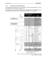
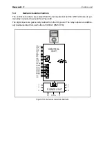
Table 24. Control I/O terminal signals
on relay board and connection example
5.1.2.1
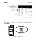
Selection of terminal functions with dip switches
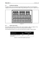
The shadowed terminals in Table 23 allow for three functional selections each with the so-
called
dip switches
. The switches have three positions, left, middle and right. The middle posi-
tion is for
Test mode
. See figure to locate the switches and make appropriate selections for
your requirements.
Figure 42. Dip switches
Relay board
Terminal
Signal
21
RO1/1
Relay output 1
22
RO1/2
23
RO1/3
24
RO2/1
Relay output 2
25
RO2/2
26
RO2/3
28
TI1+
Thermistor input
29
TI1-
From
Standard I/O board
From term.
#13
From term.
#12
RUN
RS485*
AO1
AI2
AI1
OFF
ON
Current
Voltage
Current
Voltage
Current
Voltage
* Bus termination resistor
Содержание SmartDrive HVAC
Страница 44: ...POWER CABLING Honeywell 42 4 Figure 39 ...
Страница 68: ...COMMISSIONING Honeywell 66 6 ...

