

26
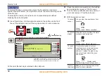
How to enable/disable a zone
How to enable/disable a zone
NA
These operations are not applicable for a Vigilon Plus
Network Node.
A zone is a subdivision of your premises that is protected by
the fire alarm system. There can be up to 128 zones configured
in a system. Any zone operation can be disabled or enabled.
You will need to know the zone number, this can be found in
the site specific documentation held by the person responsible
for the fire alarm system. From the panel:
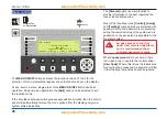
a.
Press the
MENU ON/OFF
button.
b. Press the F1 button to select
[Control]
.
c. Press the F4 button to select
[UserCode]
. At the flashing
cursor using the keypad input your PIN code and then
press the
Enter
button.
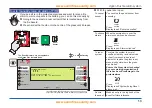
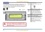
d. To disable a zone: Press the F2 button to select
[Disable]
or
press the F1 button to select
[Enable].
e. Press the F4 button to select
<etc>
and then press the F2
button to select
[Zone]
. At the flashing cursor using the
keypad input a zone number from a range 1 to 128.
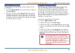
f. Press the F2 button to select
[Enter]
. Notice the action has
been processed and a message appears on the display
‘Zone n enabled’ or ‘Zone n disabled’. The Disablement
light will be illuminated upon disablement of any zone.
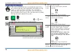
How to manually switch On / Off FARE
The fire alarm routing output via the FARE interface that
signals the Alarm Receiving Centre can be manually switched
On/Off. It may be necesssary to switch FARE to initiate fire
fighting action. From the panel:
a.
Press the
MENU ON/OFF
button.
b. Press the F1 button to select
[Control]
.
c. Press the F4 button to select
[UserCode]
. At the flashing
cursor using the keypad input your PIN code and then
press the
Enter
button.
d. Momentarily press the F4 button to select
<etc>
until
[FARE]
option is displayed.
e. Press the F4 button to select
[FARE].
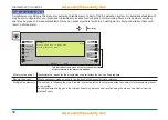
f. To switch On or Off signal to Fire Alarm Routing Equipment:
Press the F1 or F2 button to select
[Off] or [On].
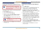
g. Press the F2 button to select
[Enter]
. Notice the action has
been processed and a message appears on the display
‘FARE activated’ or ‘FARE deactivated’.