
Document No: C-61-00003-3
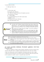
For safety distance calculation:
(
)
(
)
s
s
m
Z
C
T
T
K
S
+
+
+
×
=
where:
S
=
Safety distance (mm)
K
=
Approach speed 1600 (mm/s)
T
m
=
Maximum stopping/run-down time of the machine or system (s)
T
s
=
Response time of UAM (s)
C
=
1200-0.4×H
≧
850
H =
the height at which the protective field is mounted (mm)
1000
≧
H
≧
15× (d−50)
d
=
Minimum detectable object width (mm)
Z
s
=
UAM tolerance distance (mm)
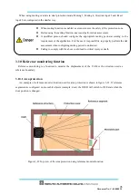
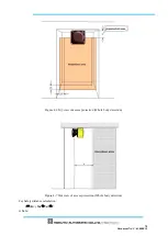
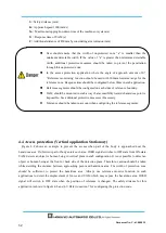
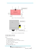
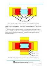
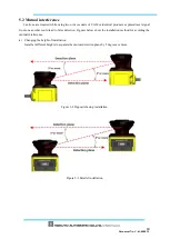
4.2 Access protection (Stationary Horizontal application with Dual
Protection zone)
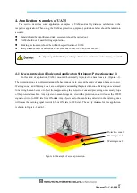
In this kind of application, UAM is mounted horizontally to simultaneously protect two hazardous areas
(Figure 4-4). Protection zones are configured around the hazardous area to prevent the entry of human
beings or object. Warning zone cannot be configuration in dual protection mode. Any objects or human
beings detected in the protection zones will switch the respective OSSD signal to OFF state from ON-state.
In this configuration it is possible to protect two equipment using a single UAM.
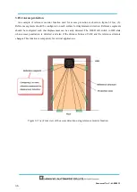
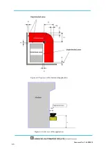
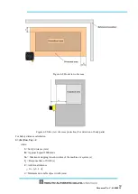
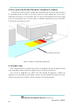
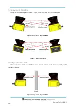
User must ensure the distance between the hazard zone edge and origin of the
protection zone “a” must be less than the minimum detectable width. In application
where the value of “a” is greater than the minimum detectable width, additional
protective measures should be taken to prevent penetration through this unprotected
area.
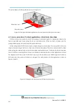
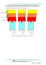
UAM should not be mounted higher than 300mm to prevent the possibility of
crawling beneath the detection plane.
For applications which require the UAM to be mounted higher than 300mm,
additional measures should be taken to prevent intrusion beneath the detection plane.
If UAM is mounted in a public area, the height of the detection plane should be
reduced to 200mm or to the height required by regulations of the local authority.
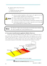
It is recommended to mark
the floor of the protection zone.
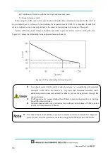
Distance tolerance should be taken into account when configuring the safety distance.
Additional tolerance should be applied when
UAM is used in the presence of high reflective
background.
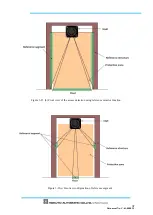
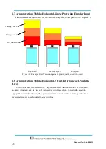
User should ensure that boundary or protective measures used are not included inside the
protected zone. They will be detected as obstacles causing the OSSD to remain in OFF-state.
User should ensure the gap of 100mm between the
protection zone and the distance of the wall
“b” to prevent the detection by the sensor.
Содержание UAM-05LP
Страница 1: ... Document No C 61 00003 3 ...
Страница 104: ... Document No C 61 00003 3 Figure 7 33 b Function Figure7 33 c Area ...
Страница 107: ... Document No C 61 00003 3 Figure 7 36 a Project report tab Figure 7 36 b Error report tab ...
Страница 148: ... Document No C 61 00003 3 13 External dimension 13 1 UAM 05LP ...
Страница 149: ... Document No C 61 00003 3 13 2 Base mounting bracket ...
Страница 150: ... Document No C 61 00003 3 13 3 Rear mounting bracket ...
Страница 151: ... Document No C 61 00003 3 13 4 Cover Protection Bracket ...
Страница 152: ... Document No C 61 00003 3 14 EC Declaration of conformity ...
Страница 153: ... Document No C 61 00003 3 ...


