

Document No: C-61-00003-3
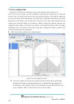
7.15.1 Area configuration by drawing tools
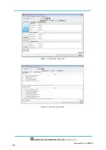
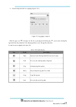
Zones can be configured using the drawing tools on the UAM project designer. Refer to Table 7-15
for the
details.
Click on the Add
button.
Select the drawing shape.
Move the cursor inside the setting possible region and draw the shape by drag and drop operation.
While drawing it is possible to switch the shapes to draw areas with combination of shapes.
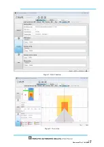
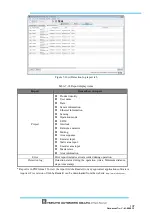
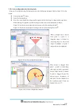
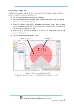
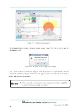
Figure 7-42 (a) shows an example of protection zone set by the selecting the line
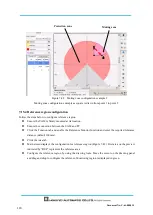
Figure 7-42 (b) shows an example of warning zone1 set by the selecting the circle
Figure 7-42 (a) Zone configuration example 1
Figure 7-42 (b) Zone configuration example 2
1
2
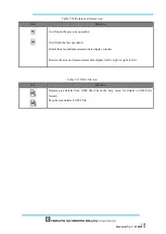
When a straight line is drawn
from point 1
→
point 2, a
triangular shape is formed by
connecting these two lines with
origin. Coordinates of point 1
and point 2 are also displayed.
When mouse is dragged from
point 1
→
point 2, a circular shape
with origin at point1 is generated.
Circular shape cannot be formed
if point is dragged beyond the
allowed region. Coordinates of
each point are also displayed on
the coordinate panel. Points are
displayed at every 2.5
°
.
1
2
Содержание UAM-05LP
Страница 1: ... Document No C 61 00003 3 ...
Страница 104: ... Document No C 61 00003 3 Figure 7 33 b Function Figure7 33 c Area ...
Страница 107: ... Document No C 61 00003 3 Figure 7 36 a Project report tab Figure 7 36 b Error report tab ...
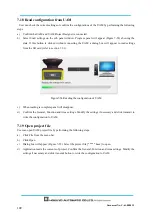
Страница 148: ... Document No C 61 00003 3 13 External dimension 13 1 UAM 05LP ...
Страница 149: ... Document No C 61 00003 3 13 2 Base mounting bracket ...
Страница 150: ... Document No C 61 00003 3 13 3 Rear mounting bracket ...
Страница 151: ... Document No C 61 00003 3 13 4 Cover Protection Bracket ...
Страница 152: ... Document No C 61 00003 3 14 EC Declaration of conformity ...
Страница 153: ... Document No C 61 00003 3 ...


