
21
Manuel d’Utilisation
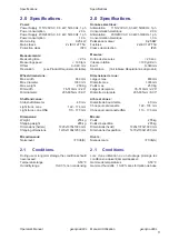
Disposition
Operator’s Manual
Layout
geodyna 980L
geodyna 980L
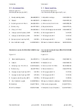
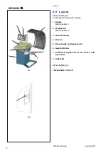
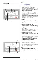
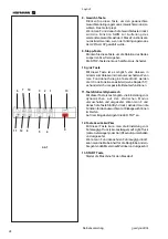
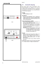
4.1
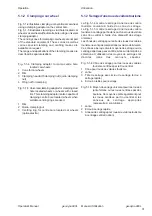
L’affichage
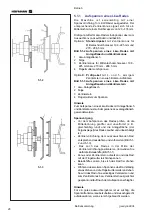
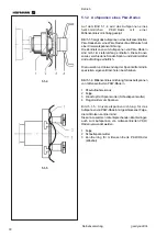
Se reporter à la Figure 4.1-1, 4.1-2.
1. Indicateurs de position de masses correctives
Les indicateurs indiquent la direction vers laquelle
l’opérateur doit tourner la roue (manuellement) après
un équilibrage.
2. Indicateur (WAP) Position de la Pose des
Masses
L’indicateur s’allume quand la roue est dans la
position correcte pour la pose des masses. Cet
indicateur est appelé indicateur WAP.
Se reporter au type de roue sélectionné avant de
poser la masse !
3. Affichage
Lors des différentes étapes du programme l’affichage
donne à l’opérateur des renseignements sur la taille
des jantes, les masses d’équilibrage, les codes
erreur, etc.
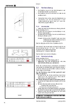
4. Indicateur “Oz” d’unités de poids
Cet indicateur s’allume si le poids est affiché en
onces au lieu de grammes (paramètre par défaut).
5. Function INT
Cet indicateur s’allume lors de la sélection du mode
de balancement “INTERNE”.
6. Compensation de la bride
Cet indicateur s’allume lors de la sélection du
compensation de la bride.
7. Indicateur de Mode Camion, Camionnette et
Voiture
Cet indicateur s'illumine de la façon suivante selon
le modalité active au moment:
- Mode Camion:
les deux Leds sont éteints.
- Mode Camionnette:
Le Led 7a est allumé
- Mode Voiture:
Le Led 7b est allumé
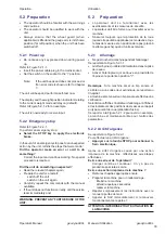
8, 12
Indicateur de position des masses.
Poser une masse agrafée ou adhésive à la position
de jante indiquée quand l’indicateur Position masse
de ce plan s’allume.
9, 10, 11
Indicateur de position des masses.
Poser une masse adhésive à la position de jante
indiquée quand l’indicateur “WAP” de ce plan
s’allume.
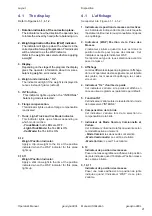
4.1
The display
Refer to Figures 4.1-1, 4.1-2.
1. Rotation indicators of the correction plane.
The indicators show the direction the operator has
to rotate the wheel (by hand) after a balancing run.
2. Weight Application Position (WAP) indicator.
The indicator will light up when the wheel is in the
correct position for weight application. This indicator
will be referred to as the WAP indicator.
Refer to the weight mode selected before applying
a weight!
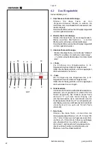
3. Display.
Depending on the stage of the program the display
gives the operator information about rim sizes,
balancing weights, error codes, etc.
4. Weight units indicator, “Oz”.
The indicator will light if the weight is displayed in
ounces instead of grams (default).
5. INT function.
This indicator lights up when the "INTERNAL"
balancing mode is selected.
6. Flange compensation.
This indicator lights up when flange compensation
is activated
7. Truck, Light-Truck and Car Mode Indicator.
This indicator lights up as follows depending on
which mode is active.
- Truck Mode:
both LEDs are OFF .
- Light-Truck Mode:
the 7a LED is ON.
- Car Mode:
the 7b LED is ON.
8,12
Weight Position Indicator.
Apply a clip-on weight to the rim at the position
indicated when the WAP indicator for this plane
lights up.
9,10,11
Weight Position Indicator.
Apply a stick-on weight to the rim at the position
indicated when the WAP indicator for this plane
lights up.
Содержание EEWBUS732A
Страница 102: ...102 geodyna 980L ...
Страница 117: ...117 geodyna980L ...
Страница 118: ...118 geodyna980L BLANK PAGE ...
Страница 119: ...119 geodyna980L BLANK PAGE ...


