29
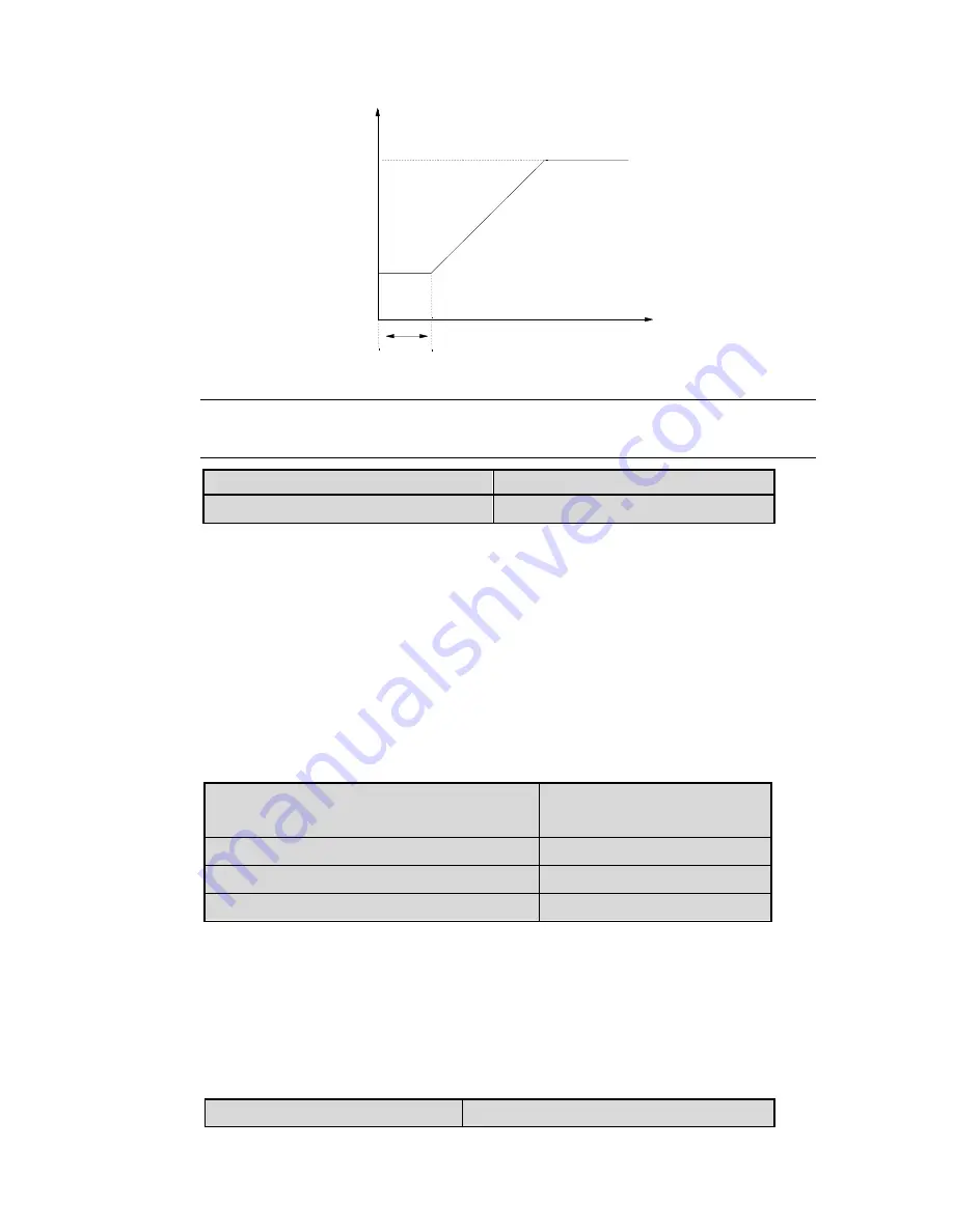
Figure 6-9 Relation of Start Freq. and Start Time
Note
:
The start frequency is not limited by lower limit of the frequency.
F2.03~F2.07 Reserved
Reserved
F2.08 Stop mode
Range
:
0
、
1
、
2
【
0
】
0
:
Decelerate to stop
When the inverter receives Stop command, it will reduce output frequency to
zero and stop within preset deceleration time.
1
:
Coast to stop
When the inverter receives Stop command, it will stop outputting frequency
and stop gradually relying on load inertia.
2
:
Decele DC braking
When the inverter receives Stop command, it will reduce output frequency
within preset Dec time. When it arrives at the frequency threshold of DC
braking, the DC braking begins. Please refer to F2.09~F2.12.
F2.09 Frequency threshold of DC braking
Range
:
0.00
~
60.00Hz
【
1.00Hz
】
F2.10 DC brake delay time
Range
:
0.00
~
10.00s
【
0.00s
】
F2.11 DC brake current at stop
0.0~150.0
%【
120.0
%】
F2.12 DC brake time at stop
0.1
~
60.0s
【
0.5s
】
DC brake starting frequency: in stop process, when the frequency is reached,
began to DC brake.
DC brake delay time: before the start of the DC brake, inverter blockade pulse,
after the delay time, began to dc brake, used to prevent current overshoot of
high-power motor brake starting time.
DC braking current: DC braking current relative to the percentage of the
frequency converter rated current.
F2.13 Dynamic braking
Range
:
0
,
1
【
0
】
t
1
Time
f
s
f
max
Freq.(Hz)
Содержание HV950-1R5G1(B)
Страница 1: ...1 HV950 Series Small Power Frequency Inverter User Manual HNC Electric Limited ...
Страница 95: ...95 ...


