3 INDIVIDUAL SPECIFICATIONS
3-35
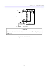
CAUTION
Power off the module before setting SW3 to avoid possible malfunctioning and
failures.
Particularly, if an external power supply is attached to a connector, remember to
switch off both the unit and the external power supply.
Fuse
Contact
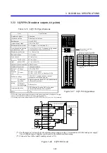
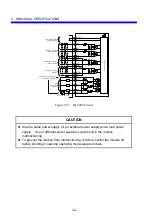
INPUTB20 000(*3)
00F
COM1
Operation indication LED
INPUTB5
INPUTB2
INPUTB1 COM1
Operation indi-
cation LED
selector switch
SW1
SW2
L
OUTPUTA2
COM2
OUTPUTA1
COM2
L
OUTPUTB20 020
OUTPUTB5
02F
OUV
OUV
Fuse (*4)
12-24 VDC (*1)
Load
SW3
Assigned
address
setup switch
01F
INPUTA5
INPUTA20 010
L
L
OUTPUTA20
030
OUTPUTA5
03F
12-24 VDC (*2)
Control circuit
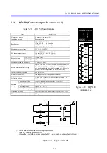
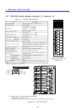
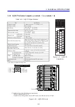
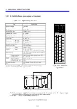
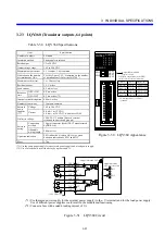
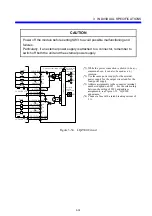
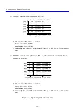
Figure 3-54 LQZ300 Circuit
(*1) While the power connection is shown to be a (-)
common above, it can also be used as a (+)
common.
(*2) Use the same power supply for the external
power supply for the output circuit and for the
load power supply.
(*3) Address assignments to the connector terminal
numbers depend on SW3. For the relationship
between the setting of SW3 and address
assignments, see Figure 3-53, “LQZ300
appearance.”
(*4) Connect a fuse with a rated breaking current of
3 A.
Содержание S10mini LQS070
Страница 1: ......
Страница 2: ......
Страница 19: ...This Page Intentionally Left Blank ...
Страница 30: ...1 BEFORE USE ...
Страница 37: ...This Page Intentionally Left Blank ...
Страница 38: ...2 KINDS AND SPECIFICATIONS OF I O MODULES ...
Страница 57: ...This Page Intentionally Left Blank ...
Страница 58: ...3 INDIVIDUAL SPECIFICATIONS ...
Страница 143: ...This Page Intentionally Left Blank ...
Страница 144: ...4 HANDLING ...
Страница 179: ...This Page Intentionally Left Blank ...
Страница 180: ...5 HANDLING I O DATA ON J NET ...
Страница 186: ...6 HANDLING I O DATA ON D Station ...
Страница 191: ...This Page Intentionally Left Blank ...
Страница 192: ...7 MAINTENANCE ...

