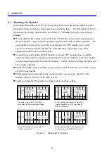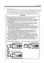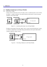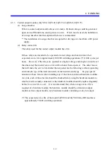
4 HANDLING
4-12
4.4 Handling Pulse Counter Modules
4.4.1 Functions
(1) Input
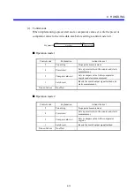
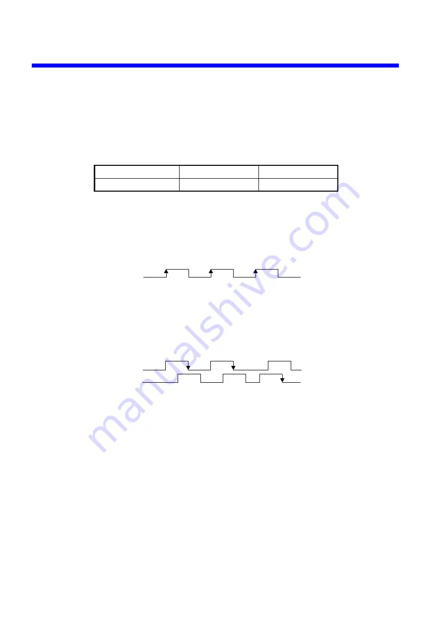
(a) Operation mode setting
Set an operation mode by shorting or opening terminal block B1 and B2.
Between B1 and B2
Open
Short
Operation mode
Operation mode 1
Operation mode 2
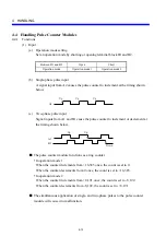
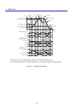
(b) Single-phase pulse input
A signal input from A2 causes the pulse counter to increment at the timing shown
below.
A2
Up
Up
Up
(c) Two-phase pulse input
Signal inputs from A1 and B1 cause the pulse counter to increment or decrement at
the timing shown below.
A1
B1
Up
Down
Up
Q
The pulse counter module functions as a ring counter.
y
In operation mode 1
When the counter increments from +16,383 once, the count is set to 0.
When the counter decrements from 0 once, the count is set to +16,383.
y
In operation mode 2
When the counter increments from +8,191 once, the count is set to -8,192.
When the counter decrements from -8,192, the count is set to +8,191.
Q
The simultaneous application of single- and two-phase pulses to the pulse counter
module will cause it to malfunction.
Содержание S10mini LQS070
Страница 1: ......
Страница 2: ......
Страница 19: ...This Page Intentionally Left Blank ...
Страница 30: ...1 BEFORE USE ...
Страница 37: ...This Page Intentionally Left Blank ...
Страница 38: ...2 KINDS AND SPECIFICATIONS OF I O MODULES ...
Страница 57: ...This Page Intentionally Left Blank ...
Страница 58: ...3 INDIVIDUAL SPECIFICATIONS ...
Страница 143: ...This Page Intentionally Left Blank ...
Страница 144: ...4 HANDLING ...
Страница 179: ...This Page Intentionally Left Blank ...
Страница 180: ...5 HANDLING I O DATA ON J NET ...
Страница 186: ...6 HANDLING I O DATA ON D Station ...
Страница 191: ...This Page Intentionally Left Blank ...
Страница 192: ...7 MAINTENANCE ...

