3 INDIVIDUAL SPECIFICATIONS
3-25
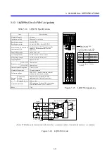
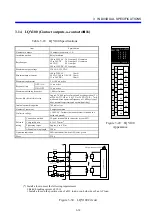
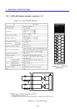
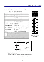
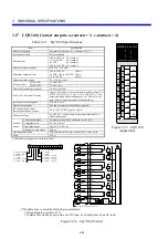
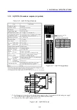
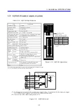
3.20 LQY300 (Transistor outputs, 32 points)
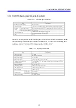
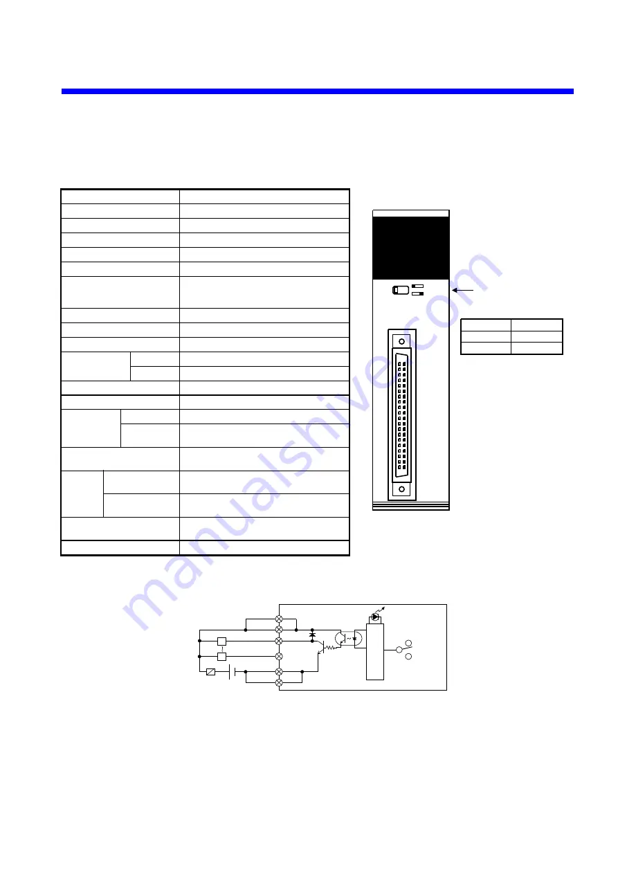
Table 3-24 LQY300 Specifications
Item Specification
Number of outputs 32
outputs
Insulation method
Photocoupler insulation
Rated output
12 to 24 VDC
Output voltage range
10.2 to 26.4 VDC
Maximum output current
0.1 A/output, 1.6 A/common (*3)
Limitation on the number of
simultaneous ONs
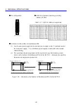
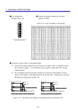
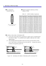
Yes (See Figure 3-43, “Limitation on the
number of simultaneous ONs for the
LQY300.”)
Maximum rush current
2 A, 10 ms or less
Residual voltage
1.5 V or less
Leak current
0.1 mA or less
Response time
OFF
→
ON
0.2 ms or less
ON
→
OFF
0.3 ms or less (*2)
Internal current dissipation
260 mA or less
Number of commons
32 outputs/common
External power
supplies
Voltage
10.2 to 26.4 VDC
Current
0.4 mA × n (12 VDC)
0.8 mA × n (24 VDC), n: Number of ONs
Dielectric voltage
1,500 VAC, 1 minute (between external
terminals in a batch and ground)
External
wiring
Connection method 40-point connector (Model FCN36
manufactured by Fujitsu Devices Inc.)
Allowable wiring
length
200 m or less
Operation indication
LED indication (lit when ON); color: green
Selection indication by SW1
Mass 150
g
(*1) Use the same power supply for an external power supply and a load power supply.
(*2) Use of a load could result in a delay by up to around 1 s.
(*3) If using a pressure-contact connector (FCN367J070-AU/F), set it to 1.0A/common.
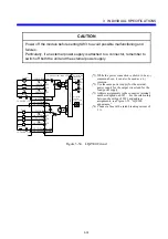
L
CN1B2 +V
Load
Fuse(*2)
12-24 VDC(*1)
Output indication LED
CN1B1 +V
CN1A2 COM
CN1A1 COM
L
CN1B20 000
CN1A5 01F
Output indication
LED selector switch
SW1
Control circuit
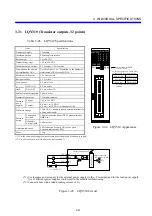
(*1) Use the same power supply for the external power supply (to the +V terminal) and for the load power supply.
Use of different power supplies could result in the module malfunctioning.
(*2) Connect a fuse with a rated breaking current of 3 A.
Figure 3-42 LQY300 Circuit
12-24 VDC
LQY300
D.OUTPUT
3
2
1
0
7
6
5
4
B
A
9
8
F
E
D
C
SW1
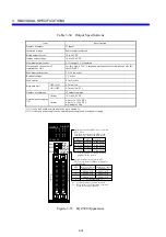
00-0F
10-1F
CN1
Output indication LED
selector switch
Switch setting
Left side
Right side
Display data (*)
X000 to 00F
X010 to 01F
(*) A starting address of Y000 is
assumed.
To display output data on the LED,
set the switch as instructed below.
Figure 3-41 LQY300 Appearance
Содержание S10mini LQS070
Страница 1: ......
Страница 2: ......
Страница 19: ...This Page Intentionally Left Blank ...
Страница 30: ...1 BEFORE USE ...
Страница 37: ...This Page Intentionally Left Blank ...
Страница 38: ...2 KINDS AND SPECIFICATIONS OF I O MODULES ...
Страница 57: ...This Page Intentionally Left Blank ...
Страница 58: ...3 INDIVIDUAL SPECIFICATIONS ...
Страница 143: ...This Page Intentionally Left Blank ...
Страница 144: ...4 HANDLING ...
Страница 179: ...This Page Intentionally Left Blank ...
Страница 180: ...5 HANDLING I O DATA ON J NET ...
Страница 186: ...6 HANDLING I O DATA ON D Station ...
Страница 191: ...This Page Intentionally Left Blank ...
Страница 192: ...7 MAINTENANCE ...


