4 HANDLING
4-8
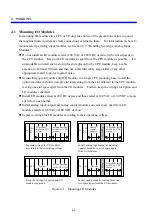
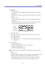
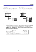
(2) Operational
overview
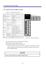
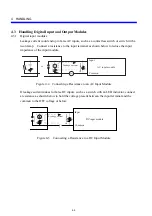
An operational overview of the digital input modules with built-in signal latches is given
below in terms of external input signals and the contact and latch reset output shown
above.
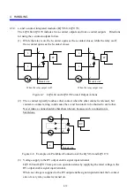
z
If an external input signal is a
narrow pulse, the contact will be
turned off by the latch reset
output.
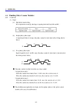
z
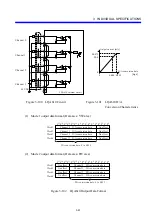
If an external input signal is a
wide pulse, the contact will
remain on even after execution of
the latch reset output as long as
the signal remains on.
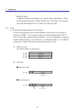
(3) Operation
timing
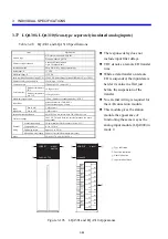
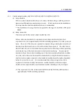
The figure below shows the relationships between the contact, latch reset output,
sequence cycles, and remote I/O transfer cycles used in conjunction with digital input
modules with built-in signal latches.
External input signal
Contact (X000)
Latch reset output
(Y000)
Remote I/O transfer timing
Built-in FF
CPU
X000
Y000
Digital input module with
built-in signal latches
External input signal
Station unit
Description of the timing chart:
①
When the external input signal (X000) is turned on, the module’s built-in FF is
latched. The input indicator LED in the module’s front panel comes on when the FF
is latched and goes out when it is reset.
②
The “on” data of the FF is transferred to the contact data item X000 in the CPU by a
remote I/O transfer.
③
The ladder program used turns on the latch reset output (Y000).
④
The output (Y000) is transferred to the module by a next remote I/O transfer and the
FF is reset simultaneously.
⑤
The data of the reset FF is transferred to the CPU’s internal memory by a next remote
I/O transfer and X000 is turned off.
⑥
The ladder program turns off Y000.
(4) Usage
precautions
y
The partition setting for the mount base on which to mount any module of this sort must
be FREE. If the setting is FIX, the module will not operate. For information on the
partition setting, refer to “S10mini CPU (Manual number SME-1-100).”
y
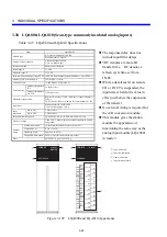
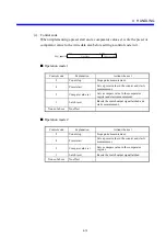
To transfer the “on” data of the external contact properly, the “off” duration of the
external contact must be at least 50 ms plus three TRCs (5 ms plus three TRCs for the
LQX211), where each TRC is a remote I/O transfer time period.
External input signal
Contact (X000)
Latch reset output
(Y000)
External input signal
Contact (X000)
Latch reset output
(Y000)
Содержание S10mini LQS070
Страница 1: ......
Страница 2: ......
Страница 19: ...This Page Intentionally Left Blank ...
Страница 30: ...1 BEFORE USE ...
Страница 37: ...This Page Intentionally Left Blank ...
Страница 38: ...2 KINDS AND SPECIFICATIONS OF I O MODULES ...
Страница 57: ...This Page Intentionally Left Blank ...
Страница 58: ...3 INDIVIDUAL SPECIFICATIONS ...
Страница 143: ...This Page Intentionally Left Blank ...
Страница 144: ...4 HANDLING ...
Страница 179: ...This Page Intentionally Left Blank ...
Страница 180: ...5 HANDLING I O DATA ON J NET ...
Страница 186: ...6 HANDLING I O DATA ON D Station ...
Страница 191: ...This Page Intentionally Left Blank ...
Страница 192: ...7 MAINTENANCE ...

