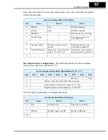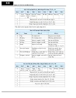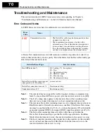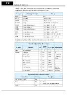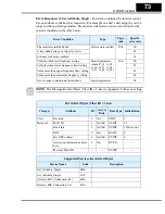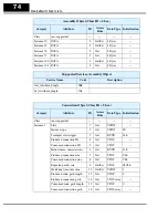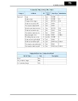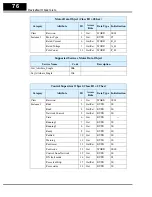
L100DN Inverter
63
Step 9 – Create a Host Computer Control Program
This section will provide an outline for constructing an example program for your host
computer control application. The example will use a simple forward and reverse
rotation for the velocity profile. Control programs for DeviceNet exist in a variety of
languages (relay ladder logic, flow charts, high-level language, etc.). Therefore, the
example program will be generic. It will use polled I/O for sending the basic commands
and to get parameters, but your program could also use explicit messaging to access any
inverter parameter.
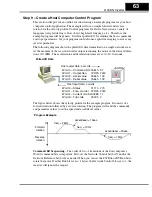
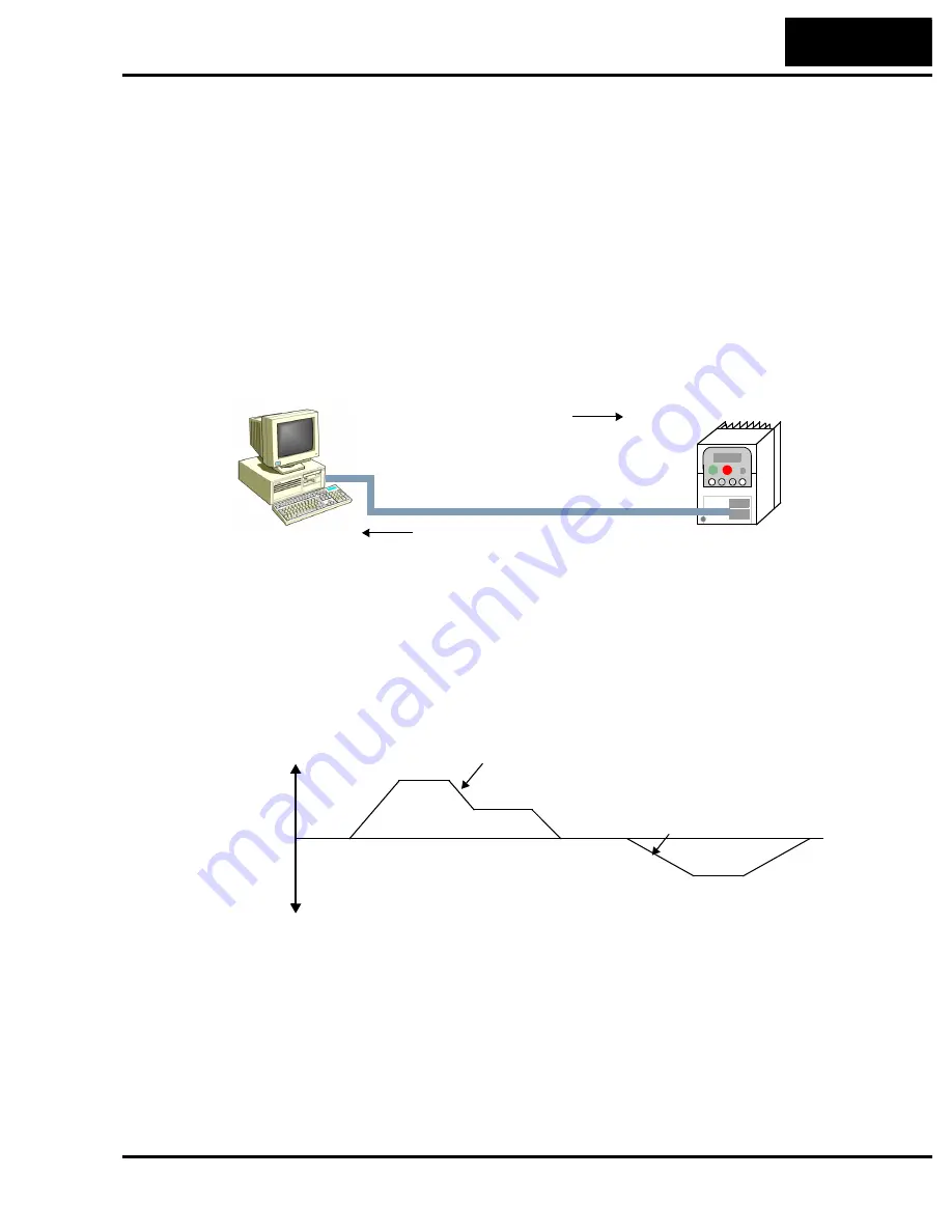
The following diagram shows the polled I/O data transmitted on a single network scan.
At the moment of the scan, the inverter output is running the motor in the forward direc-
tion at 20.00Hz. The acceleration and deceleration times are set to 10.0 seconds.
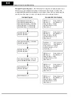
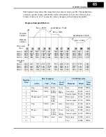
The figure below shows the velocity profile for the example program. It consists of a
forward rotation followed by a reverse rotation. The program will send the commands
and parameter values to set the speed and accel/decel values.
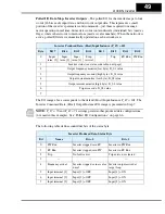
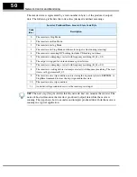
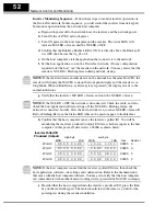
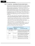
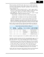
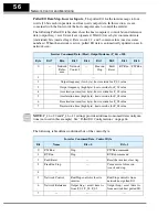
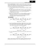
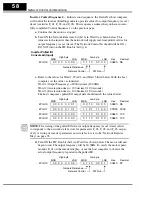
Command Bit Sequencing
– The order of 0-to-1 transitions of the host computer’s
Word 0 command bits is important. First, set the Network Control bit (bit 5) and/or the
Network Reference bit (bit 6) as needed. Then you can set the FW Run or RV Run bit to
rotate the motor. If either Run bit is set = 1
before
the Network Control bit is set = 1, the
inverter will ignore the request.
Host output data, 4 words
Word 0 – Command bits 0061h 97
Word 1 – Output freq.
07D0h 2000
Word 2 – Accel value
0064h 100
Word 3 – Decel value
0064h 100
Host input data, 4 words
Polled I/O Data
Word 0 – Status
0111h 273
Word 1 – Freq. monitor 07D0h 2000
Word 2 – Current monitor000Bh 11
Word 3 – Trip code
0000h 0
Program Example
Forward
rotation
Reverse
rotation
freq. = 25Hz
freq. = 10Hz
freq. = 15Hz
accel/decel = 10sec.
accel/decel = 20sec.
t
f
Содержание L100DN DeviceNet Series Addendum
Страница 96: ......

