Chapter 5 Instruction Specifications
5-95
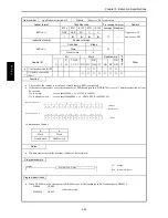
Item number
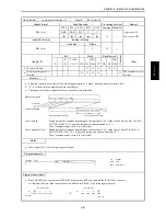
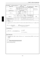
Application instructions-23
Name
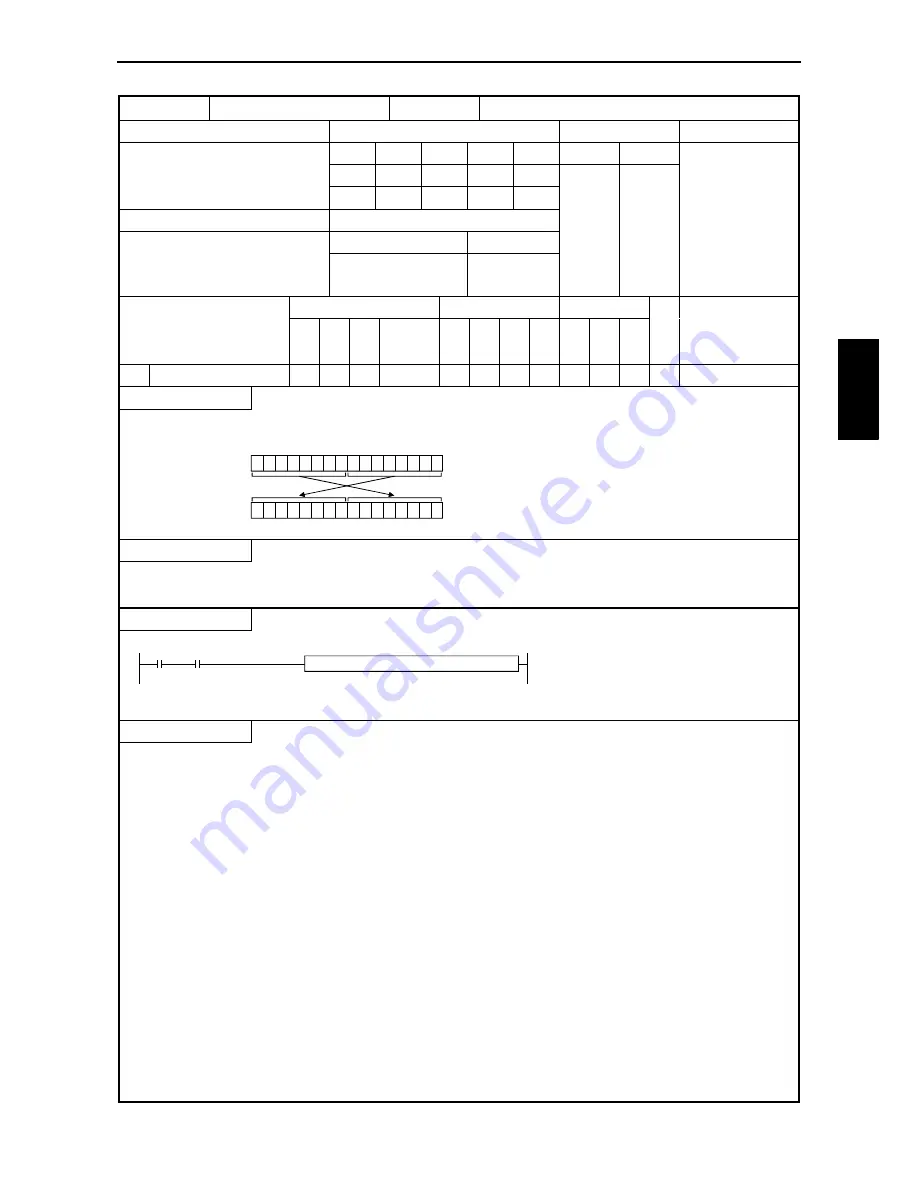
Swap
Ladder format
Condition code
Processing time (
µ
s)
Remark
R7F4
R7F3
R7F2
R7F1
R7F0
Average Maximum
SWAP (d)
DER
ERR
SD
V
C
z
z
z
z
z
Instruction format
Number of steps
25
Condition
Steps
SWAP (d)
2
Bit
Word
Double word
Usable I/O
X
Y
R,
M
TD, SS,
CU, CT
WX WY
WR,
WM TC DX DY
DR,
DM
C
o
nstant
Other
d
I/O to be exchanged
{
{
Function
•
Swaps the upper 8 bits and lower 8 bits contained in d.
0 0 0 1 1 1 0 1 0 1 1 0 1 1 0 1
0 1 1 0 1 1 0 1 0 0 0 1 1 1 0 1
(Before execution) d
(After execution) d
Notes
•
Use edge trigger as the startup condition for this instruction.
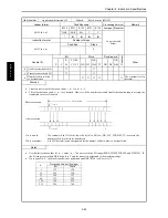
Program example
X00000
DIF0
SWAP (WR0010 )
LD
X00000
AND DIF0
[
SWAP (WR0010)
]
Program description
•
The upper and lower bits of WR0010 are swapped at the leading edge of X00000, and are stored in WR0010.
WR0010
H1234
Before execution
WR0010
H3412
After execution
Note: Since a scan is executed when there is no leading edge DIF0, the upper and lower bits of WR0010 are swapped every
time a scan is executed.
SW
A
P
(
d)
Содержание HIDIC MICRO-EH
Страница 1: ...HITACHI PROGRAMMABLE CONTROLLER APPLICATION MANUAL NJI 350B X ...
Страница 12: ...MEMO ...
Страница 14: ...Chapter 1 Features 1 2 MEMO ...
Страница 50: ...Chapter 4 Product lineup and wiring 4 18 MEMO ...
Страница 196: ...Chapter 5 Instruction Specifications 5 146 ...
Страница 263: ...Chapter 11 Communication Specifications 11 10 MEMO ...

