Chapter 8 High-speed counter, PWM / Pulse train output and Analogue I/O
8-24
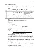
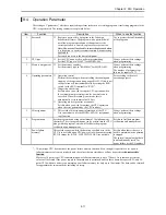
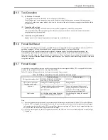
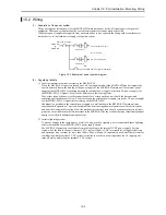
8.11 Analogue Expansion unit
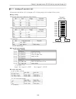
Analogue expansion module has 4 ch. of analog input and 2 ch. of analog output, which is configured by dip switches.
Range setting
Analogue input range setting (Common for all input channels.)
Sw1
Sw2
Range
Remarks
off
off
0 - 10V
Default setting
off
ON
0 -
±
10V
ON
off
0 - 20mA
ON
ON
4 - 20mA
Analogue output range setting (Common for all output channels.)
Sw3
Sw4
Range
Remarks
off
off
Default setting
off
ON
0 - 10V
ON
off
0 - 20mA
ON
ON
4 - 20mA
Conversino mode
Sw6
Conversion mode
Remarks
off
4,096 (H0FFF)
ON
4,000 (H0FA0)
Default setting
Sw5,7,8 : Set off always.
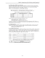
I/O assignment, data table
I/O assignment = "
FUN 0
"
WX u00
System area
Do not use this area.
WX u01
Ch.1 Input data
WX u02
Ch.2 Input data
WX u03
Ch.3 Input data
WX u04
Ch.4 Input data
Data in lower 12 bits.
Always 0 in higher 4 bits.
0000H - 0FFFH
WY u05
System area
Do not use this area.
WY u06
Ch.6 Output data
WY u07
Ch.7 Output data
Data to be written in lower 12 bits.
0000H -0FFFH
u : Unit number (1 - 4)
Example : Unit 1, Input ch.2
→
WX102 Unit 4, Output ch.7
→
WY407
In/output data table
0 - 10V / 0 - 20mA / 4 - 20mA
Mode 4000
Mode 4096
0V / 0mA / 4mA
0
0
5V / 10mA / 12mA
H07D0 (2000)
H07FF (2047)
10V / 20mA / 20mA
H0FA0 (4000)
H0FFF (4095)
-10 - +10V (only for analog input)
Mode 4000
Mode 4096
-10V
H0830 (-2000) *
H0800 (-2048) *
0V
0
0
+10V
H07D0 (2000)
H07FF (2047)
* 2's complement
SW1
→
1
O
N
OFF
ON
Dip switch
(Default setting)
Caution : Set dip switch while power off.
SW2
→
2
SW3
→
3
SW4
→
4
SW5
→
5
SW6
→
6
SW7
→
7
SW8
→
8
Содержание HIDIC MICRO-EH
Страница 1: ...HITACHI PROGRAMMABLE CONTROLLER APPLICATION MANUAL NJI 350B X ...
Страница 12: ...MEMO ...
Страница 14: ...Chapter 1 Features 1 2 MEMO ...
Страница 50: ...Chapter 4 Product lineup and wiring 4 18 MEMO ...
Страница 196: ...Chapter 5 Instruction Specifications 5 146 ...
Страница 263: ...Chapter 11 Communication Specifications 11 10 MEMO ...

