background image

HITACHI PROGRAMMABLE CONTROLLER 

Serial Communication Module (EH-SIO) 

APPLICATION MANUAL 

NJI-443F(X) 

Содержание EH-150 Series

Страница 1: ...HITACHI PROGRAMMABLE CONTROLLER Serial Communication Module EH SIO APPLICATION MANUAL NJI 443F X ...

Страница 2: ......

Страница 3: ...ault was caused by any of the items mentioned above the repair and examination cost are not covered If you have any questions regarding the warranty please contact either your supplier or the local Hitachi Distributor Depending on failure part examination might be impossible Ordering parts or asking questions When contacting us for repair ordering parts or inquiring about other items please have t...

Страница 4: ...ncorrectly a dangerous circumstance may be created resulting in possible death or severe injury CAUTION Cases where if handled incorrectly a dangerous circumstance may be created resulting in possible minor to medium injury to the body or only mechanical damage However depending on the circumstances items marked with may result in major accidents In any case they both contain important information...

Страница 5: ...o non rated power supplies may result in the outbreak of fire Ensure that all wiring procedures are performed by qualified technicians Wrong wiring may result in the outbreak of fire damage and electric shocks Ensure that the coaxial cable is shielded when installing the link module As only one side of the shielded cable is to be earthed as a basic principle attach the earth to the RXD receiving s...

Страница 6: ... 2008 09 Description to use EH SIO by EHV CPU is added Writing errors on the wire connection of the loop back cable used in the self diagnosis mode are modified Modbus Slave Mode The query example and response of function code 0x03 are corrected E 2014 09 Example of cable connection for RS 422 485 is corrected Add expansion communication setting function Simple data link Mode The sample program of...

Страница 7: ... 4 3 1 Connection of RS 232C interface 4 4 4 3 2 Connection of RS 422 485 interface 4 6 Chapter 5 Control of EH SIO 5 1 to 5 12 5 1 EH SIO Control command TRNS 9 5 1 5 1 1 Function of command 5 1 5 1 2 TRNS 9 Command format 5 3 5 2 Input Output register 5 8 5 2 1 Register configuration 5 9 5 2 2 Detail of input register 5 10 5 2 3 Detail of output register 5 12 Chapter 6 Communication Mode 6 1 to ...

Страница 8: ...6 78 6 5 5 Error detection in Hi Protocol mode 6 84 6 6 Simple data link mode 6 86 6 6 1 Abstract of simple data link 6 87 6 6 2 Performance specification 6 89 6 6 3 User project structure 6 91 6 6 4 Master configuration Initial setting of EH SIO 6 92 6 6 5 Configuration of slave station 6 99 6 6 6 Error detection in simple data link mode 6 101 Chapter 7 System setup 7 1 to 7 12 7 1 Trial Run 7 1 ...

Страница 9: ... 3 A 2 3 Error check A 4 A 2 4 Response message A 6 A 3 H series protocol Hi Protocol A 7 A 3 1 Outline A 7 A 3 2 Hi Protocol message configuration A 8 A 3 3 Basic specification of transmission control procedure A 10 A 3 4 EH SIO support task code details A 12 A 3 5 I O Code list A 27 A 4 TRNS 9 Command list A 28 A 5 TRNS 9 Return code A 29 ...

Страница 10: ...M E M O ...

Страница 11: ... Items Related manuals Manual number EHV series EHV CPU EH 150 EHV CPU Application manual NJI 481 X EH 150 EHV CPU Programming manual NJI 482 X Programming software EH 150 EHV series MICRO EHV series Ladder Programming Software Control Editor Instruction manual NJI 537 X Control Editor Polynomials Edit Manual NJI 640 X Control Editor Simulator Manual NJI 641 X EH 150 series EH 150 CPU EH 150 Appli...

Страница 12: ...SIO No Products name Model name Outlook Pcs Remarks 1 Serial I O Interface Module EH SIO 1 2 Connector for RS 422 485 Port Cable side BL3 5 6F 1 Widemuller production 3 Instruction manual NJI 442 1 Note In order to use EH SIO HX series Ver 3 5 8 26 or newer EHV series EH CPU548 Ver E402 or newer EH CPU516 Ver E202 or newer is needed Please confirm the ROM version software version of your CPU modul...

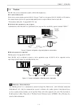
Страница 13: ...ocol is supported Modbus protocol is supported by EH SIO Since EH SIO can be configured as master or slave application range of EH 150 will be expanded such as supervising by host computer or controlling modbus slave Figure 1 2 System configuration of Modbus protocol application Reference What is Modbus The Modbus protocol is a communication protocol developed by Modicon Inc AEG Schneider Automati...

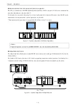
Страница 14: ...y the software version 2 1 or newer Figure 1 3 System configuration of Hi Protocol application Note Programming tools such as the LADDER EDITOR are not connectable with EH SIO Simple Data Link function The simple data link is the function to make EH SIO into a master and to exchange I O information for the slave by communication The models of PLC used as the slave is PLC which is supporting transm...

Страница 15: ...Ver E2 07 or newer EH CPU548 Ver E4 02 E4 05 EH CPU548 Ver E4 06 or newer Free Protocol Modbus Master RTU Modbus Master ASCII Modbus Slave RTU Modbus Slave ASCII Modbus Slave I O mapping Hi Protocol procedure 1 Hi Protocol procedure 2 Hi Protocol Expansion setting Simple data link Self check Not depend on the software version of CPU HX CPU Software ver 3 5 8 26 or newer supports EH SIO However how...

Страница 16: ...ersion after initial setting completion in the status of the waiting for initial setting Free protocol mode To stop CPU module Modbus master mode To stop CPU module Modbus slave mode To reset EH SIO Hi Protocol mode To reset EH SIO Simple data link mode To reset EH SIO Reference Description of I O No In this book the sign u and s is used for expressing arbitrary I O number u means unit number and ...

Страница 17: ...d I O points 128 points I O assignment LADDER EDITOR Word 4W 4W Control Editor X4Y4W SIO Unusual detection Processor abnormal Watch dog timer error System ROM RAM abnormal Communication data error parity error framing error over run and so on Supported communication mode Free protocol Modbus RTU ASCII 1 master slave Hi Protocol Transmission control procedure 1 1 2 2 Simple Data Link 1 1 This funct...

Страница 18: ...arity check framing check overrun check Input buffer full check Message error check Timeout error check Connection mode 1 1 1 N Max 32 units 1 1 1 N Max 32 units Max cable length 15 m 500 m 15 m 500 m Body side connector TM5RSB 1616 8 pin modular connector SL3 5 6 90F Pitch 3 5 6 poles with screw 1 Communication interface of Port 1 is selectable in hardware Rev 10 or newer The hardware before Rev ...

Страница 19: ...d to connect the RS 422 I F or RS 485 I F 5 Connector RS 232C Port Used to connect the RS 232C I F Selection with Communication Setting Switch 6 for Port2 RS 422 485 Port Used to connect the RS 422 I F or RS 485 I F 7 Communication setting switch The communication specification is configured by this switch Please set according to connected devices after the power off and dismounting from a base un...

Страница 20: ...en HP1 During Hi Protocol Mode 1 Lighting on Hi Protocol mode setting Port1 Green MS1 During Modbus Master Mode Lighting on Modbus Master mode setting Port1 Green 4221 Select RS 422 485 I F 2 Lighting when select the RS 422 485 I F Port1 Green SD2 Send Data Flickering when sending data Port2 Green RD2 Receive Data Flickering when receiving data Port2 Green MB2 During Modbus Mode Lighting on Modbus...

Страница 21: ...ormat Bit5 6 7 are used for setting of transmission format configuration of Port 1 configuration ON 1 2 3 4 5 6 7 8 Note If bit 7 and 8 of DIP Sw1 are ON EH SIO will start up with self check mode Communication with external devices and data transmission with CPU are not performed during self check mode execution Please refer to 8 3 Self check mode for further information Bit5 Bit6 Bit7 Transmissio...

Страница 22: ... Port2 Bit 8 is used for select of communication I F of Port 2 RS 232C or RS 422 485 RS 422 or 485 is switched by external wiring 8 ON 3 4 5 6 7 2 1 Bit8 Communication I F for Port2 ON RS 422 RS 485 Port OFF RS 232C Port Bit5 Bit6 Bit7 Transmission format configuration Data length Stop bit Kind of parity bit OFF OFF OFF 7 2 Even OFF OFF ON 7 2 Odd OFF ON OFF 7 1 Even OFF ON ON 7 1 Odd ON OFF OFF 8...

Страница 23: ...e check that the module does not separate after attaching the module 2 Remove 1 Push in the lock button 2 With the lock button pushed in pull the top of the module toward the front 3 Raise it toward the top and pull it out Note EH SIO is supported by a basic base and an extension base It does not work on the remote base where EH IOCD EH IOCD2 DeviceNet slave controller or EH IOCP EH IOCP2 Profibus...

Страница 24: ... It means that external device can be received EH SIO does not transmit data when it is Low 4 Data Terminal Ready 2 ER 1 It means that data or command is receivable Control by the user program is possible 5 Send Data SD Data from EH SIO 6 Received Data RD Data from external device 7 Data set Ready 2 DR It means that external device can operate It becomes port connection error at the time of Low 8 ...

Страница 25: ...rounding may be effective by the noise Please choose the suitable grounding method according to environment EH SIO Port 8 RS 7 DR 6 RD 5 SD 4 ER 3 CS 2 CD 1 SG PC D Sub 9pin 1 DCD 2 RxD 3 TxD 6 DSR 5 GND 4 DTR 7 RTS 8 CTS The inside of is Pin No 8 RS 7 DR 6 RD 5 SD 4 ER 3 CS 2 CD 1 SG MODEM D Sub 25pin 4 RS 2 SD 3 RD 20 ER 7 SG 6 DR 8 CD 5 CS EH SIO Port The inside of is Pin No 8 RS 7 DR 6 RD 5 SD...

Страница 26: ... used 4 SD Send data 5 SD Send data 6 RD Receive data 7 RD Receive data 8 N C Not used Signal name and Connector pin arrangement Port1 Table 4 7 Signal name EH SIO side and connector pin arrangement Port1 RS 422 485 Pin No Signal Name Symbol Signal Direction Specifications EH SIO External device 1 Ground for signal SG Ground for signal 2 Not used N C Not used 3 Not used N C Not used 4 Send data SD...

Страница 27: ...t2 Table 4 9 Signal name EH SIO side and connector pin arrangement Port2 RS 422 485 Pin No Signal Name Symbol Signal Direction Specifications EH SIO External device 1 Send data SD Data send from EH SIO 2 Send data SD Data send from EH SIO 3 Receive data RD Data received from external device 4 Receive data RD Data received from external device 5 Built in terminator TERM RD When you use built in ter...

Страница 28: ...rt one end grounding in principle However both ends grounding or no grounding may be effective by the noise Please choose the suitable grounding method according to environment EH SIO Port Port 2 6 SG 5 TERM 4 RD 3 RD 2 SD 1 SD External device 1 SG SD RD RD SD SG SD RD RD SD Terminator 100 1 2W External device n The inside of is Pin No EH SIO Port External device 1 SG SD RD RD SD External device n...

Страница 29: ...unding may be effective by the noise Please choose the suitable grounding method according to environment External device 1 External device n Terminal block Terminator The inside of is Pin No Terminator 100 1 2W SG A B A B SG 1 SG 6 RD 7 RD 5 SD 4 SD SG RD SD SD RD EH SIO Port Port 1 6 SG 5 TERM 4 RD 3 RD 2 SD 1 SD SG A B A B SG External device 1 Terminator 100 1 2W External device n The inside of...

Страница 30: ...Chapter 4 Installation 4 10 M E M O ...

Страница 31: ...d EH SIO analyzes the command sent from CPU module and executes operation according to the command 5 fundamental functions of TRNS 9 command are shown below 1 Setting of EH SIO If TRNS 9 command initial setting command is executed the communication mode of EH SIO will be set up Figure 5 1 Operation of TRNS 9 Initial setting 2 Data receiving from EH SIO If TRNS 9 command Receive command is executed...

Страница 32: ...ng and sending If TRNS 9 command Send after receiving command send data is executed EH SIO waits to receive data from external device After receiving EH SIO will send data The received data is stored in CPU module In this case data receiving and sending are operated by one command Figure 5 5 TRNS 9 Operation of TRNS 9 Send after received command EH SIO TRNS 9 Send command Data EH SIO analyzes a co...

Страница 33: ...ation of s parameter is shown below Figure 5 7 Configuration of s parameter TRNS 9 command 0 Return code When TRNS 9 command is executed an execution result is stored in high byte and the executed command is stored in low byte The execution result code is set to H00 when TRNS 9 command is executed properly About the code area at the time of abnormalities please refer to the return code in Chapter ...

Страница 34: ...ists in TRNS 9 command and EH SIO each other The command timeout is for CPU module configured in s parameter The receiving timeout is for EH SIO configured in initial setting The purpose of each timeout is different If a command timeout error occurs CPU module will close TRNS 9 command while EH SIO is still working In this case EH SIO does not receive the new command from CPU module The command ti...

Страница 35: ...a area The method to specify the data area is different according to used CPU EH CPU EHV CPU 5 Size of receiving data area Set reserved size of receiving data area Ex H000A 10 words area reserved EHV CPU S B ADRIO command Setting by ADR command EH CPU S B Type WR H000A WL H000B WM H000C I O No H0000 HFFFF ...

Страница 36: ...ial state Moreover EH SIO is returned to the state after initial setting completion All the packets that EH SIO had received till then are also cleared Please turn on when a command timeout error occurs If an initialization is completed it is set to OFF automatically It is not necessary to turn off this flag by user program 4 TRNS 9 initialization completion If the initialization of TRNS 9 command...

Страница 37: ...The I O Address designated by s B C If data is received from EH SIO by TRNS 9 command the receive data is stored in receiving data area The number of bytes of the received data is stored in the top of receiving data area The contents of received data depends on executed command Please refer to Chapter 6 Communication Mode for details Note When the received data is odd bytes low byte of the last wo...

Страница 38: ...of the treatment of the input output register by the user program or a set reset If the value of an input and output register is rewritten during TRNS 9 command execution the status of the handshake of CPU module and EH SIO may shift The handshake once shifted does not return to normal unless it carries out the initial of the TRNS 9 command If initial setting is completed by EH SIO at the time of ...

Страница 39: ...ailure occurs in the system of EH SIO WX u s 3 CPU EH SIO CPU Read System area for port 2 Before initial setting Software version In free protocol mode Number of receive packets In dedicated procedure mode Error code In Simple data link mode Error code WY u s 4 CPU EH SIO CPU Write Control register for port 1 The data for CPU module controlling a port 1 is set Set by CPU module or user WY u s 5 CP...

Страница 40: ...BE1 Out Buffer 1 Empty It is set to 1 when the send buffer for port 1 is empty 0 IBE1 In Buffer 1 Exist It is set to 1 when data is in the receive buffer for the port 1 Bit Abbreviation Name Contents of each flag 31 XCNT2 X CoNTinue flag It is set to 1 while having transmitted the data of the port 2 to CPU 30 XHS2 X HandShake flag It is set to 1 when ready for sending the data of the port 2 to CPU...

Страница 41: ...ective packets of the data received in the port 1 3 Modbus master mode Not used H0000 fixed 4 Modbus slave mode The newest error code 2 5 Hi Protocol mode The newest error code 3 6 Simple data link mode The newest error code 4 1 The number of the data which EH SIO made one packet However when an error occurs to receiving data error information is also treated as one packet 2 Error code at receivin...

Страница 42: ...o 64 System Area Used by system Bit Abbreviation Name Contents of each flag 95 YCNT2 Y CoNTinue flag It is set to 1 when there is a continuation of the data sent to EH SIO port 2 from CPU 94 YHS2 Y HandShake flag It is set to 1 when sending data to EH SIO port 2 from CPU 93 YCV2 Y Command Valid flag It is set to 1 when the command to a port 2 is decided 92 Used by system 91 PRST2 Port2 ReSeT Pleas...

Страница 43: ...next paragraph for a detailed explanation of the communication mode Basic operation of EH SIO Operation of EH SIO is shown in the following figure Figure 6 1 Basic operation of EH SIO EH SIO CPU module Power ON RUN TRNS 9 Initial setting Communication mode configured TRNS 9 Data send Data sending TRNS 9 Data receive Data receiving TRNS 9 Query send Query sending Response receiving Processing of th...

Страница 44: ...unication is controlled by TRNS 9 command In the case of modbus slave mode and Hi Protocol mode a system performs automatically from the watch of a request to response transmission In the case of simple data link mode the I O information of data link area is automatically updated by the system In addition in case of modbus slave mode Hi Protocol mode simple data link mode operation works even if C...

Страница 45: ...EH SIO receives one or more packets in a receiving buffer the indication of receiving packet in input register will be added If CPU module executes TRNS 9 data read command in this state EH SIO will send the oldest packet from a receiving buffer to CPU module and this area in receiving buffer is left as empty In addition only one packet can be passed per the data read command In order to have all ...

Страница 46: ...or etc is detected error information is shown on the LED display and operation stops When error in receiving data parity error framing error etc is detected error information is shown on the LED display and the information is stored in a receiving buffer as one packet When the packet of error information is read the error code is stored in a return code area In addition the errors of receiving dat...

Страница 47: ...unication port of EH SIO as free protocol mode by using TRNS9 command STEP 2 Data receiving and Data transmission are performed according to the devices to connect Regarding initial setting data receiving and data sending detailed explanation are shown in subsequent paragraphs Initial setting Data sending Sending only Sending after receiving Receiving after sending Data receiving TRNS 9 TRNS 9 TRN...

Страница 48: ...rom CPU module and sent it and a function which changes the character of receiving data and passes it to CPU module The following are the three types of conversion types supported 1 CPU EH SIO Through no change 2 CPU Binary EH SIO ASCII Binary ASCII Conversion 3 CPU Binary EH SIO Binary Binary through 3 Start character Optional When the message composition has a start character a start character m...

Страница 49: ... data bytes The number of bytes of the data sent to EH SIO is specified Since the setting parameter is fixed to seven words the number of transmission data bytes should be set to 14 bytes 14 H000E 2 Communication mode specification When you using free protocol mode please set to H0000 1 No of send data byte Fixed 4 Start character 6 Check code calculation type 2 Free protocol mode Fixed 3 Message ...

Страница 50: ...Initial setting error 1 Check code is calculated for a data part 2 Check code is calculated for a data part and a stop character part When a start character is not specified EH SIO will start receiving by any data When a stop character is not specified EH SIO will stop receiving by interval time Reference Message composition If message composition is registered only data part is handled by user pr...

Страница 51: ...a conversion function Specify the conversion type as below Table 6 4 Registration data conversion type list No Set Value Data conversion type 1 Hxxx0 Through no conversion 2 Hxxx1 Binary ASCII conversion CPU Binary EH SIO ASCII 3 Hxxx2 Binary through CPU Binary EH SIO Binary Others Initial setting error Through type no conversion The data stored in sending data area are transmitted as is and the r...

Страница 52: ...ng data area This conversion type uses DLE 0x10 for discernment of a control code a start character and stop character Upon transmission DLE is added in front of control code and 0x10 data and transmitted Then upon data receiving DLE is removed from received data and passed to CPU module Figure 6 11 Example of Binary Through Type Ex Start character STX 0x02 Stop character CR 0x0D when data part is...

Страница 53: ...racter is CR H0DFF Case of 2 bytes Specify the start character with one word The effective range is same as start character Ex Stop character is CR LF H0D0A 6 Check code calculation type EH SIO corresponds to various types of check codes When using the message composition containing a check code please choose the calculation type from Table 6 5 If a check code is registered EH SIO will perform gen...

Страница 54: ...it is recognized as the end of data The maximum timeout is HFFFF Note Please set the data interval time shorter than the 7 receiving timeout time Execution of initial setting After the required s parameter and parameter for send data are stored please turn on the command execution flag t 0 End of initial setting 1 Completed properly H0000 is stored in return code area s 0 and completion flag t 1 g...

Страница 55: ...osition others WR103 H02FF Start character WR104 H0D0A Stop character WR105 H0003 Check code calculation type WR106 100 Receiving timeout time WR107 H0000 Data interval time R7E3 Sending data area parameter for initial setting R7E3 M0 S DIF TRNS 9 command execution WR7 H0000 Initial setting command WR8 200 Command timeout time WR9 H000A I O address of sending data area WRA H0100 WR100 WRB H000A I ...

Страница 56: ...k code stop character Modem line control Hxx0x RS ER regular ON Data conversion type Hxxx0 Through type Start character H02FF STX 02 Stop character H0D0A CR LF 0D0A Check code calculation type H0003 Byte ASCII Sum Receiving timeout interval 100 1000 ms Data interval time Disabled because of stop code used Note TRNS 9 is initialized at the 1st scan So other settings and operations should be execute...

Страница 57: ...d with other signals In addition ER and RS can be selected as automatic or manual but even when manual operation is chosen the operation follows the flow chart above For example when the RS flag is ON the control register will be ON and the actual signal line will not turn ON until the DR signal comes ON Reference When a control line is not used When there is no control signal in the connected dev...

Страница 58: ...t used in this command Please set dummy parameters in s 9 to s A Figure 6 15 s parameter format Free protocol Data receiving Execution of data read Please turn on command execution flag t 0 after storing the parameter required for s parameter End of data read 1 Receiving data are read When receiving data are read properly completion flag t 1 goes on and H0010 is set to return code area The read da...

Страница 59: ...ast data are kept Figure 6 17 Receiving data area format Free protocol Note In case of error at data reading previous data remain in receiving data area Therefore if a program which refers to the data part of receiving data area directly is created old data will be referred to when errors occur By the methods as below users can check if receiving command is executed properly 1 The completion flag ...

Страница 60: ...area TRNS 9 WY214 WR0 M0 R7E3 Data receive command set TRNS 9 command start TRNS 9 command WR100 H000E No of send data byte WR101 H0000 Communication mode WR102 H0100 Message composition etc WR103 H0000 Start character WR104 H0DFF Stop character WR105 H0000 Check code calculation type WR106 200 Receiving timeout time WR107 H0000 Data interval time R7E3 R7E3 M0 S DIF0 s parameter Sending data area ...

Страница 61: ...WR7 H0000 Initial setting command WR8 200 Command timeout time DR9 ADR WR100 I O address of sending data area WR100 DRB ADR WR200 I O address of receiving data area WR200 WRD H0400 Size of receiving data area R7E3 s parameter Data receive command set TRNS 9 command start TRNS 9 command 1 WX212 DIF WR100 H000E No of send data byte WR101 H0000 Communication mode WR102 H0100 Message composition etc W...

Страница 62: ...e even if one packet is received in port 1 of slot 1 unit 2 those data are read after WR200 Note As for the system area WXus2 and 3 of an input register software version is displayed till completion of initial setting When you create a user program which refers to the number of packets please use it combining the initial setting completion flag XICx of a status register The contents of initial set...

Страница 63: ... execution of the TRNS 9 command Set the number of send data bytes into the top of the sending data area Data should become after the next word Figure 6 19 Sending data area format Free protocol Data sending Execute data sending Please turn on command execution flag t 0 after storing the parameter required for s parameter and send data for the sending data area Return code H0020 Command s s 7 s 8 ...

Страница 64: ...End of data sending When EH SIO sends data properly completion flag t 1 will be ON and H0020 will be set to return code area If the transmission of data is failed error flag t 2 turns on and error code is stored in the upper byte of return code area ...

Страница 65: ...ease refer to command H0020 sending only Execution of command Please turn on command execution flag t 0 after storing the parameter required for s parameter and send data for the send data area The end of receiving after data transmission When EH SIO sends data properly completion flag t 1 will be ON and H0021 will be set to return code area If the transmission of data is failed error flag t 2 tur...

Страница 66: ...sage composition registered in the initial setting If EH SIO detects an unusual factor in the received data transmission will not be performed and the abnormal contents will be returned to CPU module as a return code Data to transmit Please refer to command H0020 sending only Execution command Please store the parameter required for the s parameter set the number of send data bytes and the transmi...

Страница 67: ...R0 M0 R100 0 WR100 H0003 WR101 H4C4F WR102 H4E00 WR7 H0021 Receiving after sending command M0 1 R7E3 Send data command set TRNS 9 command start WR100 H000E No of send data byte WR101 H0000 Communication mode WR102 H0000 Message composition others WR103 H0000 Start character WR104 H0000 Stop character WR105 H0000 Check code calculation type WR106 100 Receiving timeout time WR107 10 Data interval ti...

Страница 68: ...00 Not used Check code calculation type H0000 Not used Receiving timeout interval 100 1000 ms Data interval time 10 Detect end of data according to 100ms interval TRNS 9 WY4A5 WR0 M0 WR7 H0000 Initial setting command WR8 200 Command timeout time DR9 ADR WR100 I O address of sending data area WR100 DRB ADR WR200 I O address of receiving data area WR200 WRD H0400 Size of receiving data area R7E3 s p...

Страница 69: ... 3 and 4 is shown blow Refer to section A 5 TRNS 9 Return code for a list of error codes Table 6 6 Free protocol mode abnormalities detected in EH SIO No Error code Name Error level Details 1 H81 Non supported command error Warning Command not supported Initializing duplicates 2 H82 Initial setting error Warning Parameter error in initializing Initializing incomplete 3 H83 Transmission data error ...

Страница 70: ...e time specified by EH SIO 6 H8F Sending timeout error Warning EH SIO did not complete transmission of data by within the time interval Monitoring time is fixed by the system It cannot be changed 7 H91 Inaccurate data content of message Warning A message containing inaccurate data was transmitted and received Example The wording is correct as a telegram message but the contents of the data are abn...

Страница 71: ...dware error is detected by the self diagnostic function of EH SIO operation will stop if a serious failure occurs In this case please reboot the power or push the reset switch on the front of the module 2 Query error An error code is stored in the return code area of TRNS 9 command when data error is detected or when communication errors a parity error abnormalities in a check code etc are detecte...

Страница 72: ... communication port of EH SIO as Modbus master mode by using TRNS9 command STEP 2 The program which transmits query is performed By one TRNS 9 command execution it carries out to the response receiving from a slave Regarding initial configuration and query sending response receiving detailed explanation is shown in subsequent paragraphs Initial setting Query sending Response receiving TRNS 9 TRNS ...

Страница 73: ...r mode H0010 2 Modbus transmission mode Select RTU mode 0 or ASCII mode 1 Only RTU mode is supported by software ver 1 0 3 Receiving timeout interval Specify timeout if necessary The definition of timeout is as follows 1 No response with in specified time 2 Data receiving not completed within specified time s parameter of TRNS 9 command for initial setting Initializing command specified as s 7 is ...

Страница 74: ...end of query and the end of received response H0000 Timeout disabled H0000 Timeout enabled in setting time x 10ms The maximum timeout is HFFFF Figure 6 26 Monitoring of receiving timeout Execution of initial setting After the required s parameter and parameter for sending data are stored please turn on the command execution flag t 0 End of initial setting 1 Completed properly H0000 is stored in re...

Страница 75: ...ta area R7E3 s parameter TRNS 9 command WR100 H0006 No of send data byte WR101 H0010 Communication mode WR102 H0000 Modbus transmission mode WR103 50 Receiving timeout time R7E3 Sending data area Parameter for initial setting R7E3 M0 S DIF TRNS 9 command execution TRNS 9 WY325 WR0 M0 WR7 H0000 Initial setting command WR8 200 Command timeout time WR9 H000A I O address of sending data area WRA H0100...

Страница 76: ...of unit 3 Items Setup value Setup contents Communication mode H0010 Modbus master mode Modbus transmission mode H0000 RTU mode Receiving timeout time 50 500 ms Note TRNS 9 is initialized at the 1st scan So other settings and operations should be executed after the 2nd scan Initial setting and communication are operated by TRNS command However do not use TRNS command twice or more for one port So e...

Страница 77: ...one cycle of TRNS 9 command is from sending to receiving When any errors from the slave response are detected or an exception response is returned an error flag t 2 turns on The exception response data exception code is stored in the receiving data area Note EH SIO checks the validity of the response code the function code and the check code only Therefore if the above mentioned item is correct th...

Страница 78: ...mmand start R100 X3229 For initial setting TRNS 9 WY325 WR0 M0 WR7 H0000 Initial setting command WR8 200 Command timeout time WR9 H000A I O address of sending data area WRA H0100 WR100 WRB H000A I O address of receiving data area WRC H0200 WR200 WRD H0400 Size of receiving data area WR100 H0006 No of send data byte WR101 H0010 Communication mode WR102 H0000 Modbus transmission mode WR103 50 Receiv...

Страница 79: ...ster mode Modbus transmission mode H0000 RTU mode Receiving timeout time 50 500 ms TRNS 9 WY325 WR0 M0 WR7 H0000 Initial setting command WR8 200 Command timeout time DR9 ADR WR100 I O address of sending data area WR100 DRB ADR WR200 I O address of receiving data area WR200 WRD H0400 Size of receiving data area R7E3 s parameter TRNS 9 command WR100 H0006 No of send data byte WR101 H0010 Communicati...

Страница 80: ...ddress Specified data address does not exist in the slave 03 Illegal data value Data value is not allowed for the slave 04 Slave device failure An unrecoverable error occurred in the slave 05 Acknowledge Although query is recognized it takes time to reply To prevent timeout error 06 Slave device busy Processing of previous query Reference Modbus data address Data address must be specified for data...

Страница 81: ... state of receiving data area 1 Completed properly Figure 6 29 Receiving data area format Function code 0x01 When a response is received properly from the slave completion flag t 1 will be ON and the coil information is stored in the address specified by the query from LSB Since the information on the coil is handled per byte 0 is stored in the remaining area when the information on a coil does no...

Страница 82: ...for exception response When there is no response from a slave or an abnormal factor is detected in the response error flag t 2 turns on an error code is stored in the return code area of the s parameter and the number of receiving data is cleared to H0000 Data other than the number of receive data bytes maintains previous values Please refer to section 6 3 5 Error detection in modbus master mode f...

Страница 83: ...letion flag t 1 will be ON and the input status information is stored in the address specified by the query from LSB same as function code 0x01 Data unit of EH SIO is one word same as function code 01 2 Receiving exception response When an exception response is received error flag t 2 turns on and the receiving data area is as follows Figure 6 34 Receiving data area format Function code 0x02 Excep...

Страница 84: ...de 0x03 When a response is received properly from the slave completion flag t 1 will be ON and the holding register information is stored in the address specified by the query from head word 2 Receiving exception response When an exception response is received error flag t 2 turns on and the receiving data area is as follows Figure 6 37 Receiving data area format Function code 0x03 Exception respo...

Страница 85: ...e 0x04 When a response is received properly from the slave completion flag t 1 will be ON and the input register information is stored in the address specified by the query from head word 2 Receiving exception response When an exception response is received error flag t 2 turns on and the receiving data area is as follows Figure 6 40 Receiving data area format Function code 0x04 Exception response...

Страница 86: ...tate of receiving data area 1 Completed properly When performance is properly completion flag t 1 will be ON and nothing is stored in receiving data area A properly execution code is stored in a return code s 0 2 Receiving exception response When an exception response is received error flag t 2 turns on and the receiving data area is as follows Figure 6 42 Receiving data area format Function code ...

Страница 87: ...ceiving data area 1 Completed properly When performance is properly completion flag t 1 will be ON and nothing is stored in receiving data area A properly execution code is stored in a return code s 0 2 Receiving exception response When an exception response is received error flag t 2 turns on and the receiving data area is as follows Figure 6 44 Receiving data area format Function code 0x06 Excep...

Страница 88: ...to change by hexadecimal number H0001 to H07F0 5 Values of coils Set the value of coils to change ON 1 OFF 0 Ex Change the status of all eight coils from 17th in the slave No 39 to ON The head address of Sending data area WR100 WR100 H0008 WR101 H270F WR102 H0010 WR103 H0008 WR104 H00FF Note Be sure to set an even number for number of send data bytes For example when the number of the coils to set...

Страница 89: ...s follows Figure 6 46 Receiving data area format Function code 0x0F Exception response 3 Other errors except for exception response When there is no response from a slave or an abnormal factor is detected in the response error flag t 2 turns on an error code is stored in the return code area of the s parameter and the number of receiving data is cleared to H0000 Data other than the number of recei...

Страница 90: ...H5A10 WR102 H0064 WR104 H0002 WR105 H1234 WR106 H5678 2 The state of receiving data area 1 Completed properly When performance is properly completion flag t 1 will be ON and nothing is stored in receiving data area A properly execution code is stored in a return code s 0 2 Receiving exception response When an exception response is received error flag t 2 turns on and the receiving data area is as ...

Страница 91: ...ng The parameter value or the number is wrong 4 H84 Receiving buffer full Warning The EH SIO input buffer is full with receiving data Table 6 13 Modbus master mode errors detected in communication No Error code Item Error level Details 1 H8A Parity error Warning EH SIO detected parity error in response 2 H8B Framing error Warning EH SIO detected framing error in response 3 H8C Overrun error Warnin...

Страница 92: ...e and the meanings of EH SIO are shown below Table 6 14 Supported function and meanings Function Function Modbus Original Corresponding Hitachi PLC I O 01 0x01 Read Coil Status Read continuous n points of bit output Y 02 0x02 Read Input Status Read continuous n points of bit input X 03 0x03 Read Holding Registers Read continuous n points of internal register WR 04 0x04 Read Input Registers Read co...

Страница 93: ...ue by I O refreshment N continuation read or N continuation set cannot be performed ranging over I O from which classification differs Reference Merit demerit of the I O mapping 1 Merit Since I O which can be accessed in function code was decided as shown in Table 6 14 EH SIO cannot be accessed at I O which does not correspond to a function code Moreover although the address of I O is specified by...

Страница 94: ...r code will be stored and the response will not be sent out Since EH SIO keeps operation rebooting or resetting is not necessary Note EH SIO does not send a response in case of error Be sure to make fail safe system like timeout in master side if necessary 3 Exception response If the slave receives the abnormal query like that the request is to read a non existent coil or register the EH SIO will ...

Страница 95: ...d EH SIO will operate automatically by completion of initial setting of Modbus slave mode Specific user program is not required to make communication Once EH SIO specified Modbus slave mode even if CPU module stop operation has been done EH SIO continues Modbus communication To stop this operation of EH SIO reset operation of EH SIO is required Regarding initial setting detailed explanation is sho...

Страница 96: ...lt The I O mapping function has not been supported in software ver 1 0 Set H0000 in software ver 1 0 6 I O mapping information Word Please specify when you assign a register word data to I O other than a default The I O mapping function has not been supported in software ver 1 0 Set H0000 in software ver 1 0 Parameter of TRNS 9 command for initial setting Command number of initial setting in s 7 i...

Страница 97: ...t is WM as same as the operation of software ver 2 6 or before please set H0011 When target internal output is WR please set H0111 3 Modbus communication mode Select modbus ASCII mode or RTU mode Table 6 16 Modbus communication mode Value Communication mode H0000 RTU mode others ASCII mode Not supported in software ver 1 0 Reference Function code 03 06 16 in Modbus protocol is the function code fo...

Страница 98: ...rd A top address is specified from low byte of 1st word and 2nd word Ex In case of Y20316 1st word H0120 2nd word H0310 3 Address offset of Modbus protocol 1 word 1 class It specifies where the top address of I O of 2 is mapped H0000 to HFFFF Note 2 3 of parameter prepares the number set up with the number of table divisions When you use software ver 1 0 or when you do not use I O mapping please s...

Страница 99: ...ot use I O mapping please set the number of bit table divisions as H0000 When the number of table divisions is 0 the parameter of I O classification I O No and address offset is unnecessary Execution of initial setting Set execution flag t 0 after s parameter and the sending data area configured Note Max number of modbus slave modes is 8 modules per CPU module Both ports can work as Modbus slave i...

Страница 100: ...R104 H0000 I O mapping B Not used WR105 H0000 I O mapping W Not used R7E3 Sending data area Parameter for initialization M0 S TRNS 9 command execution R0 DIF R7E3 X4A29 TRNS 9 WY4A5 WR0 M0 WR7 H0000 Initial setting command WR8 200 Command timeout time WR9 H000A I O address of sending data area WRA H0100 WR100 WRB H000A I O address of receiving data area WRC H0200 WR200 WRD H0002 Size of receiving ...

Страница 101: ...EH SIO is completed initial setting completion flag X4A29 is set ON Once Modbus slave mode is configured this mode will be kept after CPU is in STOP status In this sample program initial setting program works only when initial setting has not been configured yet Items Setup value Setup contents Communication mode H0011 Modbus slave mode Modbus mode H0000 Modbus RTU mode Device address H01xx No 01 ...

Страница 102: ...ddress of receiving data WRC H0200 WR200 WRD H0002 Size of receiving data area S R0 DIF1 R7E3 R7E3 M0 R7E3 s parameter Sending data area Parameter for initialization TRNS 9 command TRNS 9 Execution WR100 H0022 No of send data byte WR101 H0011 Communication mode WR102 H0001 Modbus mode RTU WR103 H180A Address waiting time WR104 H0000 I O mapping B Not used WR105 H0004 I O mapping W Division number ...

Страница 103: ...cation mode WR102 H0001 Modbus mode RTU WR103 H180A Address waiting time WR104 H0000 I O mapping B Not used WR105 H0004 I O mapping W Division number4 R7E3 Sending data area Parameter for initialization M0 S TRNS 9 execution R0 DIF R7E3 X4A29 WR106 H0A00 WR107 H0000 WR108 H0000 WR109 H0B00 WR10A H0000 WR10B HD000 WR10C H0B00 WR10D H1000 WR10E HE000 WR10F H0C00 WR110 H0000 WR111 HF000 R7E3 I O No W...

Страница 104: ... setting completion flag X4A29 is ON initial setting program is not executed Items Setup value Setup contents Communication mode H0011 Modbus slave mode Modbus mode H0001 Modbus ASCII mode Device address H18xx No 24 Waiting time Hxx0A 100 ms 10 10ms I O mapping Bit H0000 Not used I O mapping Word H0004 Used The number of table divisions 4 H0000 HD000 HE000 HF000 HFFFF WR0 WL0 WL1000 WM0 HC400 Modb...

Страница 105: ... u 4 s A and bit No 10 the start address is H4A0A 2 Response Response is sent back automatically according to query The meaning of the data field bit with 1 for ON and 0 for OFF the first LSB data will be in the state of the specified I O number Data is handled as 1 byte If data less than 1 byte is requested the rest part will be 0 Note If requested address or a part of data is not assigned as out...

Страница 106: ...il head address upper 0 1 Number of data bytes 0 2 Coil head address lower 0 A Coil data upper C B Number of coils upper 0 0 Coil data lower 0 A Number of coils lower 0 E Error check CRC Error check CRC Data in Y110 Y117 is stored in high byte LSB Y110 and data in Y118 Y123 is stored in low byte Y110 OFF ON ON ON OFF OFF ON ON OFF ON OFF ON ON OFF OFF Y123 OFF ON ON OFF OFF Y131 OFF OFF OFF OFF OF...

Страница 107: ...LSB data will be in the state of the specified I O number Data is handled as 1 byte If data less than 1 byte is requested the rest part will be 0 Note If requested address or a part of data is not assigned as input exception response will be returned 3 Example Read the status of X2408 X2415 8 points in the slave 05 Query Response Field name Example HEX Field name Example HEX Slave address 0 5 Slav...

Страница 108: ...ress Note If requested address or a part of data is not assigned as WR range exception response will be returned 3 Example Read the status of WR9A02 WR9A03 2 words in the slave 10 Query Response Field name Example HEX Field name Example HEX Slave address 0 A Slave address 0 A Function code 0 3 Function code 0 3 Holding register head address upper 9 A Number of data bytes 0 4 Holding register head ...

Страница 109: ... a part of data is not assigned as WM range exception response will be returned 3 Example Read the status of WM1F2 WM1F4 3 words in the slave 18 Query Response Field name Example HEX Field name Example HEX Slave address 1 2 Slave address 1 2 Function code 0 4 Function code 0 4 Input register head address upper 0 1 Number of data bytes 0 6 Input register head address lower F 2 Input register data 1...

Страница 110: ...es H390A 2 Response When a query is processed normally the response data will be the same as the query In broadcasting no response will be returned Note If requested address is not assigned as output exception response will be returned 3 Example Set ON to Y1021 in the slave 21 Query Response Field name Example HEX Field name Example HEX Slave address 1 5 Slave address 1 5 Function code 0 5 Functio...

Страница 111: ...ddress should specify I O number of WM For WM20 WR20 the address is specified as H0020 2 Response When a query is processed normally the response and the query become the same In broadcasting a response is not returned Note If requested address is not assigned as internal output exception response will be returned 3 Example Write H19CF to WMA2 WRA2 in the slave 27 Query Response Field name Example...

Страница 112: ...cessed normally the response data will be the same as the query In broadcasting no response will be returned Note If requested address is not assigned as output exception response will be returned 3 Example Write following data to Y4A00 Y4A15 16 points in the slave 31 Query Response Field name Example HEX Field name Example HEX Slave address 1 F Slave address 1 F Function code 0 F Function code 0 ...

Страница 113: ...the same as the query In broadcasting no response will be returned Note If requested address is not assigned as internal output WR exception response will be returned 3 Example Write following data to WR100 WR101 2 words in the slave 51 Query Response Field name Example HEX Field name Example HEX Slave address 3 3 Slave address 3 3 Function code 1 0 Function code 1 0 Register head address upper 0 ...

Страница 114: ...7 Modbus slave mode initial setting error list No Error code Item Error level Details 1 HFF CPU error Operation of EH SIO stops due to serious error of CPU module 2 Watchdog timer error Serious error MPU in EH SIO does not work due to watchdog timer error 3 H03 OS system error Serious error Error is detected in system OS of EH SIO 4 H51 Number of entries over Warning Slot number is wrong The numbe...

Страница 115: ...Warning EH SIO detected a parity error in query received message 5 H8B Framing error Warning EH SIO detected a framing error in query received message 6 H8C Overrun error Warning EH SIO detected an overrun error in query received message 7 H8D Check code error Warning EH SIO detected a validity abnormality in the check code of query received message 8 H8E Receiving timeout error Warning Data recei...

Страница 116: ...e If EH SIO receive request task code from host computer EH SIO decodes the request task code and transfers the request to CPU module When EH SIO receives the response from CPU module EH SIO sends back the response to host computer according to the Hi Protocol message frame procedure Figure 6 55 Hi Protocol basic function Table of task code supported by EH SIO Following table shows the supported r...

Страница 117: ...ontinue the operation and will not require power rebooting or resetting Reference What is Hi Protocol Hi Protocol is the dedicated communication procedure of H and EH series A request command issued by host computer is called a request task code and a response from PLC is called a response task code In this sense Hi Protocol is called Task Code Communication also Since PLC status can be monitored ...

Страница 118: ...rence Figure 6 56 Performance Transmission control procedure 1 Figure 6 57 Performance Transmission control procedure 2 Reference When using several EH SIOs with Hi Protocol mode it is recommended to balance using both port numbers EH SIO has two ports Port1 and Port2 To get better performance using Hi Protocol the number of Port1 and Port2 should be same For example mounting two EH SIO modules on...

Страница 119: ...fter initial setting is completed EH SIO will operate Hi protocol mode automatically Specific user program is not required to make communication Once EH SIO specified Hi Protocol mode even if CPU module stops operation EH SIO continues Hi Protocol communication To stop this operation of EH SIO reset operation is required for EH SIO Regarding initial setting detailed explanation is shown in next se...

Страница 120: ... communication mode Specify Hi Protocol Mode 2 Usage of station number Select usage of task code with station number or without station number 3 Station number In case of task code communication with station number specify station number Parameters of TRNS9 command for initial setting Initializing command specified as s 7 is H0000 Be sure to set parameters in the sending data area s 9 to s A accor...

Страница 121: ...nsmission control procedure 2 Simple Transmission control procedure 2 HFE Standard Transmission control procedure 1 using expansion communication setting HFF Simple Transmission control procedure 2 using expansion communication setting 2 Usage of station number Specify the type of task code communication with station number or without station number Table 6 22 Usage of station number Value Type of...

Страница 122: ... bytes 8 H0008 3 Specification of Transmission procedure Usage of station number HFExx Standard procedure xx station number or HFFxx Simple procedure xx station number 1 Length of data Value b0 Length of data 0 7 bits 1 8 bits 2 Communication speed Value b3 1 Communication speed b3 b2 b1 0 0 0 300 bps 0 0 1 600 bps 0 1 0 1 200 bps 0 1 1 2 400 bps 1 0 0 4 800 bps 1 0 1 9 600 bps 1 1 0 19 200 bps 1 ...

Страница 123: ...xistence of checksum in transmission data from host Value b8 Existence of checksum 0 Not existence 1 Existence This parameter is convenient for the situation that host send the request with wrong checksum though procedure without checksum is selected ...

Страница 124: ...is turned ON and error code is stored into return code area Please remove the cause of error by reference to the return code in 6 5 5 Error detection in Hi Protocol mode Sample program initial setting 1 Ladder program EH CPU TRNS 9 WYA5 WR0 M0 WR7 H0000 Initial configuration command WR8 200 Command timeout time WR9 H000A I O address of sending data area WRA H0100 WR100 WRB H000A I O address of rec...

Страница 125: ...his sample program initial setting program works only when initial setting has not been configured yet Items Setup value Setup contents Communication mode H0020 Hi Protocol mode Type of task code H0001 With station number Station number H27xx Station number 27 TRNS 9 WYA5 WR0 M0 WR7 H0000 Initial setting command WR8 200 Command timeout time DR9 ADR WR100 I O address of sending data area WR100 DRB ...

Страница 126: ...ode Name Error level Detail contents 1 HFF CPU error EH SIO operation has been stopped due to the error detection of CPU module L RES ON was done 2 Watch dog timer error Fatal Failure MPU of EH SIO can t operate according the system program anymore EH SIO has detected watch dog timer error of MPU 3 H03 OS system error Fatal Failure EH SIO has detected an error of system OS 4 H51 Over flow error of...

Страница 127: ...een used for the port specified as SLAVE function or easy data link function 5 H8A Parity error Warning Parity error has been detected in the received data by EH SIO 6 H8B Framing error Warning Framing error has been detected in the received data by EH SIO 7 H8C Over run error Warning Over run error has been detected in the received data by EH SIO 8 H8D Check code error Warning Check code error ha...

Страница 128: ...mple data link is RS 422 the protocol is Hi Protocol Communication procedure 2 is used The PLCs EHV series MICRO EHV series EH CPU316A 516 548 MICRO EH series which have these functionality can be connected Since the link system is handled only by master EH SIO no other setting is necessary on slave PLCs than communication parameter configuration Figure 6 61 Simple data link mode basic operation N...

Страница 129: ...a 4 Master sends the data to other slaves than slave A one by one 5 Master writes the data to slave A s area in the master module 6 Master repeats 3 to 5 procedure according to the registered slave station number and repeats 1 to 6 Figure 6 62 Link area image of Standard mode High speed link mode The member of slaves and data link area is registered by initial setting EH SIO operates according to ...

Страница 130: ... operation of data link is stopped also If hardware error is detected reboot the PLC power or push reset switch of EH SIO on front panel to restart It is not required to reboot the power for each slave unit 2 Communication error If EH SIO detects communication error parity error or check code error or does not receive response indicates error with showing slave station nummber CPU module will turn...

Страница 131: ...me Data refresh time depends on scan time of master CPU transmission speed the number of slave stations and size of data link area The following is the formula of data refreshing time 1 Standard mode RReq RRes WReq WRes n SWT n RWT n HST n n The number of stations RReq Transmission time of reading request from master to slave depends on transmission speed RRes Transmission time of reading response...

Страница 132: ...f the CPU module status is in STOP In this case CPU scan time should be calculated as 120ms EH SIO sends a request to registered slave stations Therefore if a slave that participates in registration cannot return a response abnormality occurrence cable unconnected etc the refresh time will be longer than usual ...

Страница 133: ...de by using TRNS 9 command EH SIO will operate automatically after initial setting completed No other user program is necessary than initial setting Once EH SIO specified simple data link mode even if CPU module is in stop mode EH SIO continues simple data link communication To stop this operation of EH SIO reset operation of EH SIO is required Go on to the next section for further information abo...

Страница 134: ...e for slave response 3 Waiting time between stations Specify waiting time between stations 4 Setting of data link area Specify internal output I O type and start address of data link operation 5 Number of words occupied by master Specify data size word for master station 6 Number of stations and words number of each stations Specify station number of slaves and data size word s Parameters of TRNS ...

Страница 135: ...receiving request to sending response Slave station will wait specified time multiplied by 10ms and reply to EH SIO The possible value for configuration is 0 no wait time to 15 H000F waiting 150ms and if the set value is out of this range initial setting error will be detected Figure 6 68 Waiting time for slave response Note This parameter is recommended to be configured as 20 ms or more for stabl...

Страница 136: ...e and address is configured by 2 words This address will be the starting address of data link area same both for Master and Slave station Ex Incase of WRA00 should be start address 1st word H000A 2nd word H0A00 6 Number of words for master Specify the data size of master in BCD Valid range is H02 to H48 If the value is less than H1 or more than H49 or including A to F characters initial setting er...

Страница 137: ...be detected 2 Number of words for slave station Specify the data size of slace station in low byte in BCD The valid range is H00 to H48 If the value is more than H49 or including A to F characters the iinitial setting error will be detected Ex In case of station number 01 16 words station number 14 4 words and station number 29 32 words make data link 1st word H0116 2nd word H1404 3rd word H2932 W...

Страница 138: ...ial setting 1 Ladder program EH CPU TRNS 9 WY215 WR0 M0 WR7 H0000 Initial setting command WR8 200 Command timeout time WR9 H000A I O address of sending data area WRA H0100 WR100 WRB H000A I O address of receiving data area WRC H0200 WR200 WRD H0002 Receiving data area size WR100 H0012 No of send data byte WR101 H0030 Communication mode WR102 H0002 Waiting time for slave response WR103 H0002 Waitin...

Страница 139: ... TRNS 9 command WR100 H0012 No of send data byte WR101 H0030 Communication mode WR102 H0002 Waiting time for slave response WR103 H0002 Waiting time for switching station No WR104 H000A Setting data link area WR105 H1000 WR106 H0016 Number of words occupied by master WR107 H0132 Station number word of slave station WR108 H0208 Station number word of slave station WR109 H0324 Station number word of...

Страница 140: ...r CPU is in STOP status In this sample program initial setting program works only when initial setting has not been configured yet Items Setup value Setup contents Communication mode H0030 Simple data link mode standard Waiting time for slave response H0002 20 ms 2 x 10ms Waiting time for switching station number H0002 20 ms 2 x 10ms Setting data link area H000A Specify WR1000 H1000 Number of word...

Страница 141: ...al termination register Note CPU module which has not RS 422 interface and transmission procedure 2 can t be used as slave station Implement wiring according to RS 422 interface It is possible to use RS 485 instead of RS 422 but the protocol error error code 6A may be detected during the communication The operation will be continued even if this error code is displayed 2 In case of MICRO EH as sla...

Страница 142: ... 422 transmission procedure 2 with station number by Control Editor 4 In case of MICRO EHV as slave station Configure the serial port on option board as transmission procedure 2 with station number by Control Editor If MICRO EHV is used as slave in simple data link mode please use the option board with RS 422 communication interface ...

Страница 143: ...IO operation has been stopped due to the error detection of CPU module L RES ON was done 2 Watch dog timer error Fatal Failure MPU of EH SIO can t operate according the system program anymore EH SIO has detected watch dog timer error of MPU 3 H03 OS system error Fatal Failure EH SIO has detected an error of system OS 4 H50 Invalid command specifying error Warning TRNS 9 command has been executed a...

Страница 144: ...3 H03 OS system error Fatal Failure EH SIO has detected an error of system OS 4 H50 Non valid command error Warning TRNS 9 command has been used for the port specified as SLAVE function or simple data link function 5 H8A Parity error Warning Parity error has been detected in the received data by EH SIO 6 H8B Framing error Warning Framing error has been detected in the received data by EH SIO 7 H8C...

Страница 145: ...n good The procedure of trial run Figure 7 1 Flow of the trial RUN Please check whether it is set up correctly about transmission speed transmission format configuration and communication I F of port 2 Please check the state display LED of EH SIO The state at the time of the power supply ON Please check that RUN LED of CPU module is lighting Please check that LED which shows the setup communicatio...

Страница 146: ...There are four bits showing errors in a status register Errors can be checked by the ladder program the monitor by peripheral unit etc WX r u s 0 1 Bit 15 31 14 30 13 29 12 28 11 27 10 26 9 25 8 24 7 23 6 22 5 21 4 20 3 19 2 18 1 17 0 16 Name XCNT XHS XIC XRS XMDE XCDE XDTE CD CS DR IFS TII PTE OBE IBE A B A For Port 1 B For Port 2 Figure 7 2 Status Register Table 7 3 Status register abnormal disp...

Страница 147: ...Command timeout error Warning OFF OFF OFF OFF 13 H40xx Receiving data overflow Warning OFF OFF OFF OFF 14 H50xx Designated Invalid command Warning OFF OFF OFF OFF 15 H51xz Number of entries over Warning OFF OFF OFF OFF 16 H81xx Command not supported Warning OFF ON OFF OFF 17 H82xx Initial setting error Warning OFF ON OFF OFF 18 H83xx Transmission data error Warning OFF ON OFF OFF 19 H84xx Receive ...

Страница 148: ... mode A A NO YES NO YES NO YES NO YES NO YES A Modbus slave mode NO YES Hi Protocol mode NO YES Please refer to the flow of Modbus master mode Please refer to the flow of Modbus slave mode Reference EH SIO does not start communication unless initial setting is completed Initial setting completion of the communication port can be checked with the XIC flag of the status register For port 1 Xus13 u U...

Страница 149: ...is impossible to detect data reception In this case an error does not occur Data send and receive Send and receive OK Replace the module Check the return code and the program YES NO Transmission speed OK YES Transmission format configuration OK YES Connection of communication cable OK YES Status of external device normal Send and receive OK NO OK YES OK Please set up a communication setting switch...

Страница 150: ...eed OK YES YES YES Status of slave device normal Sending data Query OK YES NO OK Please set up a communication setting switch again NO Please set up a communication setting switch again NO Please connect a communication cable correctly NO Please change the slave device to a normal state NO Exception response YES NO Please improve the contents of sending data query Please improve the designated add...

Страница 151: ... Query transmission Response transmitted Replace the module YES NO Transmission speed OK YES YES YES Status of host normal Contents of query OK YES NO OK Please set up a communication setting switch again NO Please set up a communication setting switch again NO Please connect a communication cable correctly NO Please change the host to a normal state NO Exception response YES NO Please reconfirm t...

Страница 152: ...NO YES Abnormal task code NO YES Please improve a request task code YES A A B B B OK Supported CPU Type Version YES NO Replace the CPU module Reference The cause which cannot communicate has many wiring mistakes of a communication cable When communication does not work please check connection of a cable first EH SIO of software ver 2 0 does not support transmission control procedure 2 If it s conf...

Страница 153: ...nnection of a cable Replace the CPU module Reboot the power several times If this does not solve replace the module A Supported CPU Type Version YES NO Replace the CPU module A Connection of communication cable OK YES Please connect a communication cable correctly NO Participating flag ON Reference The cause which cannot communicate has many wiring mistakes of a communication cable When communicat...

Страница 154: ...or newer Free Protocol NG 1 OK OK Modbus Master RTU NG 1 OK OK Modbus Master ASCII NG 1 OK OK Modbus Slave RTU NG 1 OK OK Modbus Slave ASCII NG 1 OK OK Modbus Slave I O mapping NG 1 OK OK Hi Protocol procedure 1 NG 5 NG 5 OK Hi Protocol procedure 2 NG 4 NG 4 NG 6 Simple data link NG 7 NG 7 OK 4 EH SIO Software ver 2 1 EH CPU Function of EH SIO EH CPU516 Ver E2 00 E2 01 EH CPU516 Ver E2 02 E2 06 EH...

Страница 155: ...not supported Please check the command of s parameter 17 H82xx Initial setting error Please check whether initial setting of a port has ended 18 H83xx Transmission data error Please check whether it is satisfactory to the value stored in sending data area 19 H84xx Receive buffer full Please execute the read command and read the data of a receiving buffer 20 H85xx Connect error Please check the sta...

Страница 156: ...Chapter 7 System setup 7 12 M E M O ...

Страница 157: ...splay of EH SIO LNK 2 Under simple data link mode operation Lighting SD1 Port1 Data being transmitted Blinking RD1 Port1 Data being received Blinking MB1 Port1 Under Modbus master slave mode operation Lighting HP1 2 Port1 Under Hi protocol mode operation Lighting MS1 Port1 Under Modbus master mode operation Lighting 4221 3 Port1 Used I F RS 422 RS 485 Lighting Port1 Used I F RS 232C OFF SD2 Port2 ...

Страница 158: ...64 V AC AC power supply 21 6 to 26 4 V DC DC power supply Tester Installation and connecting areas 1 All modules are securely fixed 2 All connectors fit snugly 3 All screws are tight 4 All cables are normal No defects Tighten Check insertion Tighten Ambient environment 1 Temperature 2 Humidity 3 Other 0 to 55 C 20 to 90 RH no condensation No dust foreign matter vibration Spare parts Check number o...

Страница 159: ... whether LSI of a system operates properly 5 Port1 RS 232C Loop back check Signal line of the communication port 1 RS 232C is checked by loop back data Port1 RS 422 485 Loop back check Signal line of the communication port 1 RS 422 485 is checked by loop back data 6 Port2 RS 232C Loop back check Signal line of the communication port 2 RS 232C is checked by loop back data 7 Port2 RS 422 485 Loop ba...

Страница 160: ...2 485 are required to perform self check mode Wiring of a loop back connector is shown in the following figure 1 For port1 Same connection for RS 232C and RS 422 485 2 For port2 for RS 232C 2 For port2 RS 422 485 port Note Please prepare loop back connectors 8 1 5 6 4 7 3 8 EH SIO side 8 1 5 6 4 7 3 8 EH SIO side 6 1 2 4 1 3 Attached connector ...

Страница 161: ...o communication ports 4 Turn on the PLC power 5 Self check will start Please check LED status as shown Table 8 4 8 5 Note In case of the product before software ver 2 0 LED check mode will start If a power supply is turned on all LED except WDE LED will light up and will turn off Then some LED blink The module consists of precise electronic products When you set up this switch please don t touch a...

Страница 162: ...2 422 1 ROM Check 2 RAM Check 1 3 RAM Check 2 4 LSI Check 5 Port1 Check 6 Port2 RS 232C Check 7 Port2 RS 422 485 Check 8 LED Check 9 Software version display Turn ON Conditional turn ON is the LED part which is not printed at all Table 8 5 LED display under self check Hardware Rev 10 or newer No LED Display Check item MB1 HP1 MB2 HP2 MS1 4221 MS2 4222 1 ROM Check 2 RAM Check 1 3 RAM Check 2 4 LSI ...

Страница 163: ...f of LED by users In addition WDE LED is not turned on at the LED check Software version display If a check is completed software version indication blinks every 1s A software version is displayed as shown in the following figure Figure 8 2 Display of software version Ex In case of software ver 2 1 MB2 and 4222 blink 1s cycle SERIAL I O EH SIO MB1 HP1 MB2 HP2 MS1 4221 MS2 4222 SERIAL I O EH SIO MB...

Страница 164: ...Chapter 8 Daily and Periodic Inspection 8 8 M E M O ...

Страница 165: ...0 1 0 0 4 TC4 EOT DC4 4 D T d t 0 1 0 1 5 TC5 ENQ TC8 NAK 5 E U e u 0 1 1 0 6 TC6 ACK TC9 SYN 6 F V f v 0 1 1 1 7 BEL TC10 ETB 7 G W g w 1 0 0 0 8 FE0 BS CAN 8 H X h x 1 0 0 1 9 FE1 HT EM 9 I Y i y 1 0 1 0 10 FE2 LF SUB EOT J Z j z 1 0 1 1 11 FE3 VT ESC K k 1 1 0 0 12 FE4 FF IS4 FS L l 1 1 0 1 13 FE5 CR IS3 GS M m 1 1 1 0 14 SO IS2 RS N n It displays on the upper right It displays on the upper rig...

Страница 166: ...ts of check filed of command response data error check field The message configuration of query and response message are shown in the following figure Query message from master Device address Function code Query data Error check Response message from slave Device address Function code Response data Error check Figure A 1 The query response cycle There are two kinds of serial transmission modes ASC...

Страница 167: ... T4 A 2 2 Function code The purposes of query from master to slave depends on function code in message frame as below Table A 4 The function code which EH SIO is supporting Function code Function Modbus Original EH SIO slave mode operation 01 0x01 Read Coil Status Read continuous n points of bit output Y 02 0x02 Read Input Status Read continuous n points of bit input X 03 0x03 Read Holding Registe...

Страница 168: ...s will be discarded 2 Subtract the final field value from FF hex to produce the ones complement 3 Add 1 to produce the twos complement LRC calculation Target data exist YES NO LRC H00 LRC LRC Target data LRC 2 s complement END Figure A 2 Calculation procedure of LRC Ex When coil information is read from the coil address 0000 16 bits of a slave Device No 08 Query Field Name HEX Device No 08 0000 10...

Страница 169: ...111 XOR 1111 1111 1111 1101 XOR 1000 0001 0011 1001 Shift right 1 0111 1111 1111 1110 1 Shift right 1 0100 0000 1001 1100 1 XOR 0xA001 1010 0000 0000 0001 XOR 0xA001 1010 0000 0000 0001 1101 1111 1111 1111 1110 0000 1001 1101 Shift right 2 0110 1111 1111 1111 1 Shift right 2 0111 0000 0100 1110 1 XOR 0xA001 1010 0000 0000 0001 XOR 0xA001 1010 0000 0000 0001 1100 1111 1111 1110 1101 0000 0100 1111 ...

Страница 170: ...de and data fields The device No of a slave is set to the device No field like a normal response The same function code as query is set to a function code and the MSB is set to 1 by which a host can detect an exception response The exception code which shows the exceptional contents is set to the data field An exception code and description are shown in the following table Table A 5 Exception code...

Страница 171: ...ransmission control procedure 1 Transmission control procedure 2 TCP IP Task code combination IEEE 802 3 The functions seen from users Logical level Data link level Physical level I O Control CPU Control Memory Read Write Response EH ETH CPU module EH SIO Figure A 4 Outline of H EH series communication protocol In case of serial communication physical level is RS 232C RS 422 or RS 485 The procedur...

Страница 172: ...code Max 495 byte Standard H protocol with station No Transmission control procedure 1 S T X TM St No L U M P Task code Sum C R ASCII code Max 505 byte Simple H protocol with station No Transmission control procedure 2 S T X TM St No Task code Sum C R ASCII code Max 497 byte Note LUMP is a network address to identify CPU from a host Since EH SIO does not support to access remote CPU LUMP should be...

Страница 173: ...LINK modules smaller slot number is loop No 1 U Station No of Link module M Module No It is used for error detection etc In case of address from CPU it is always 00 P Port No It is used for error detection etc In case of address from CPU it is always 00 In case of EH SIO Please set as L FF U FF M 00 P 00 In case of transmission control procedure 2 LUMP address is not used Task code Refer to follow...

Страница 174: ...ycle In case of CPU Busy EOT ENQ 1 EOT LUMP C R Host PLC T M LUMP Task code S u m S T X C R ACK ENQ 1 ENQ 1 S T X Res ponse LUMP C R Figure A 5 Transmission control procedure 1 Communication sequence diagram Host PLC T M Task code S u m S T X S T X C R Response The minimum cycle In case of CPU Busy C R Host PLC T M Task code S u m S T X C R S T X Response C R Figure A 6 Transmission control proced...

Страница 175: ... error 3 04 Over run error 4 07 Receiving buffer error 5 08 Receiving time out error 6 05 Protocol error 7 06 ASCII error 8 02 Sum error Low If a request includes invalid parameter Illegal sub command or non existing I O address etc PLC returns a task code with error information such as task code error or not executed Response Task code error or Not executed Host PLC ACK T M LUMP Task code S u m S...

Страница 176: ...F This value is counted up only when memory writing has occurred and the WRITE occupation is canceled indicating the number of times WRITE occupation has occurred This value is H00 upon power up CPU status 4 digits b area details response to the subcommand H00 15 14 13 12 11 10 9 8 7 6 5 4 3 2 1 0 0 0 0 0 0 0 0 0 bit0 RUN STOP flag bit1 Halt status flag bit3 Error status flag bit7 Battery error fl...

Страница 177: ...0200 128 k steps EHV CPU128 Data memory capacity d H0094 22 kW EH CPU516 H0100 49 kW EH CPU548 H00F0 228kW EHV CPU 128 64 32 16 3 System software version response to the subcommand H02 a H 1 0 b a Response task code H00 when executed normally b Version 4 digit BCD This is the version of the system software ROM for CPU 4 Read error code subcommand H03 a H 1 0 b a Response task code H00 when execute...

Страница 178: ... digit Decimal place 2 digit EH CPU516 548 H0610 EHV CPU H0803 e CPU Hardware information 2 digit hexadecimal EH CPU516 548 H0001 EHV CPU H0001 f Supported high function module information 2 digit hexadecimal EH CPU516 548 H000E EHV CPU H0006 g Supported language information 2 digit hexadecimal EH CPU516 548 H0001 EHV CPU H0001 h CPU function information 2 digit hexadecimal EH CPU516 548 H0000 EHV...

Страница 179: ...User program version H00 to HFF 1 READ occupation subcommand H01 This command is used when the local station is not occupying the CPU if performing tasks such as reading the user program monitoring and setting the data memory or the I O 2 WRITE occupation subcommand H02 This command is used when writing the user program if the local station is not WRITE occupying the CPU This command cannot be use...

Страница 180: ...his chapter With forced cancel if there are modification in the parameter area the same processing as parameter modification completion processing is performed refer to the task code H27 as well as the canceling of memory occupation 1 Forced cancel of all occupation subcommand H00 All occupation is canceled unconditionally so when this command has been executed the peripheral that is reading the u...

Страница 181: ...imal hexadecimal conversion chart c Number of bits H01 to HF0 1 to 240 Number of words H01 to H78 1 to 120 Response format a H 4 0 b a Response task code H00 when executed normally For task codes other than the normal task codes refer to the response list by task code at the end of this chapter b Monitor data Bit data 1st point 2nd point 3rd point 8th point Binary image H00 to HFF bit7 bit0 Number...

Страница 182: ...words H01 to H64 1 to 100 d Set reset data Bit data 1st point 2nd point 3rd point 8th point Binary image H00 to HFF bit7 bit0 Number of points 8 When the number of set reset points is less than 8 points the open bits are set to 0 H00 to HFF Word data Binary image H0000 to HFFFF Number of words H L 1st word Nth word Response format H 4 2 a a Response task code H00 when executed normally For task co...

Страница 183: ...int 1st word Nth point Nth word a Number of bits Number of words H01 to H3C 1 to 60 b I O code refer to the I O code table c I O number refer to I O number decimal hexadecimal conversion chart Response format 1st bit 1st word a H 4 4 Nth bit Nth word Monitor data b b a Response task code H00 when executed normally For task codes other than the normal task codes refer to the response list by task c...

Страница 184: ...O code table c I O number refer to I O number decimal hexadecimal conversion chart d Set reset data Bit data 0 ON 1 OFF 0 0 0 Word data H0000 to HFFFF Response format H 4 5 a a Response task code For task codes other than the normal task codes refer to the response list by task code at the end of this chapter The EH 150 returns H00 normal execution even for I Os that are out of range Example Write...

Страница 185: ...ion chart c Number of bits H01 to HF0 1 to 240 Number of words H01 to H78 1 to 120 Response format a H A 0 b a Response task code H00 when executed normally For task codes other than the normal task codes refer to the response list by task code at the end of this chapter b Monitor data Bit data 1st point 2nd point 3rd point 8th point Binary image H00 to HFF bit7 bit0 Number of points 8 When the nu...

Страница 186: ...ion chart c Number of bits H01 to HC8 1 to 200 Number of words H01 to H64 1 to 100 d Set reset data Bit data 1st point 2nd point 3rd point 8th point Binary image H00 to HFF bit7 bit0 Number of points 8 When the number of set reset points is less than 8 points the open bits are set to 0 H00 to HFF Word data Binary image H0000 to HFFFF Number of words H L 1st word Nth word Response format H A 2 a a ...

Страница 187: ...mber of bits Number of words H01 to H3C 1 to 60 b I O code refer to the I O code table c I O number refer to I O number decimal hexadecimal conversion chart Response format 1st bit 1st word a H A 4 Nth bit Nth word Monitor data b b a Response task code H00 when executed normally For task codes other than the normal task codes refer to the response list by task code at the end of this chapter b Mon...

Страница 188: ...ords H01 to H28 1 to 40 b I O code refer to the I O code table c I O number refer to I O number decimal hexadecimal conversion chart d Set reset data Bit data 0 ON 1 OFF 0 0 0 Word data H0000 to HFFFF Response format H A 5 a a Response task code For task codes other than the normal task codes refer to the response list by task code at the end of this chapter The EH 150 returns H00 normal execution...

Страница 189: ...is WRITE occupying CPU WRITE occupation H02 Normal execution H00 Not executable H03 Occupation code mismatch H03 Local station is READ occupying CPU Occupied by another station H08 CPU is occupied by another station Occupation mode H05 Normal execution H00 modification WRITE READ Not executable H03 Not occupied H07 Local station is not occupying the CPU Occupation mode H06 Normal execution H00 mod...

Страница 190: ...5 The requested number of points is outside the designated range Abnormal I O code H06 The requested I O type code is undefined or is an I O that cannot be forced to be set Abnormal I O No H07 The requested I O No is outside the designated range Not executable H03 Not occupied H07 Local station is not occupying CPU HA0 None Normal execution H00 Abnormal task code H01 Abnormal number of steps words...

Страница 191: ... H0C WM 0 to H7FFF 0 to H3FF H0D TC 0 to H9FF 2 559 0 to H1FF 511 H0E DIF 3 0 to H1FF 511 H0F DFN 3 0 to H1FF 511 H20 WN 0 to 1FFFF EHV CPU128 RP 0 to 7FFF Other EHV 4 1 When the frame is divided into two stages the upper part indicates the setting range of EHV CPU and the lower part indicates the setting range of EH CPU 2 As to the bit internal output R the address after R7C0 is special internal ...

Страница 192: ...d sending data Modbus H0000 H0010 Initial setting Master H0080 Sending query or sending query and receiving response Modbus Slave H0000 Function code 06 WM access H0011 WR access H0111 Initial setting to EH SIO No other command for Modbus slave mode Hi Protocol H0000 H0020 Initial setting to EH SIO No other setting command for Hi Protocol mode Simple data link H0000 Standard link mode H0030 High s...

Страница 193: ...iving data area is over the range of I O 9 H28 Area overlap error Warning Area has overlapped s parameter t parameter sending data area receiving data area 10 H30 Command time out error Warning TRNS 9 command was not completed within the specified time 11 H40 Receiving data overflow Warning Receiving data was not able to store in receiving data area 12 H50 Designated Invalid command Warning TRNS 9...

Страница 194: ...thin the time specified by EH SIO 24 H8F Timeout error Send Warning EH SIO did not complete transmission of data by within the time interval Monitoring time is fixed by the system It cannot be changed 25 H90 Error message reception Warning Error message response was received Example Modbus exception response reception etc 26 H91 Message data error Warning A message containing inaccurate data was t...

Отзывы: