background image


Operator’s / Service Manual, PRS 40 EZ 

© PRS 40 EZ  REV A 03/16/06 

190201_A 

42 

13 MAINTENANCE 

The only maintenance required is to change the batteries when required.  Also, check the mounting 
hardware daily to ensure that there is no damage.  Replace any damaged parts before operating the 
crane. 

13.1 BATTERY 

REPLACEMENT 

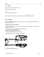
To replace the batteries, remove the 4 screws from the transmitter housing.  During battery 
replacement, use caution when opening the battery cover and transmitter to avoid damage to the 
gasket causing moisture ingress which could corrode the batteries and terminals.   Inspect the gasket 
surface on the transmitter for nicks or other damages that may prevent the gasket from sealing.  If it 
appears to be damaged, a replacement gasket should be installed.  

Install 4 fresh batteries into the proper location and direction as indicated on the battery holder. 
 
Make sure that the cardboard tube is installed as shown. 


LOOSEN 4 SCREWS  


INSPECT CONDITION OF GASKET 


BATTERY DIRECTION LABEL  


INSTALLED BATTERIES IN CARDBOARD TUBE 

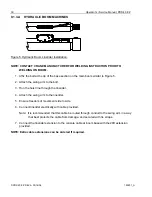
Software version 
 
Battery direction 

Содержание PRS 40 EZ

Страница 1: ...HIRSCHMANN P N 031 300 190 201 Revision A 03 16 2006 PRS 40 EZ OPERATOR S SERVICE MANUAL...

Страница 2: ......

Страница 3: ...rotected by copyright and all rights are reserved No part of this document may be photocopied reproduced or translated to another language without the prior written consent of Hirschmann Inc Hirschman...

Страница 4: ......
Страница 5: ...15 6 1 4 A2B Setup 17 7 WIND 19 7 1 1 Operation 19 7 1 2 LIMITS 20 7 1 3 Installation 20 7 1 4 Wind Setup 21 8 LOADCELL 23 8 1 1 Operation 23 8 1 2 LIMITS 24 8 1 3 Installation 25 8 1 4 Loadcell Setup...

Страница 6: ...rvice Manual PRS 40 EZ PRS 40 EZ REV A 03 16 06 190201_A 6 13 1 BATTERY REPLACEMENT 42 14 PART NUMBERS 43 14 1CONSOLE 43 14 2A2B 44 14 3 WIND 46 14 4ANGLE 47 14 5ANTENNA OPTIONS 48 14 6LINERIDER 49 14...

Страница 7: ...ng the boom out without paying attention to the hoist line can cause a two block condition 2 WARNINGS The PRS 40 EZ System is an operational aid which warns a crane operator of approaching two block c...

Страница 8: ...vision 4 1 1 Liquid Crystal Display The Liquid Crystal Display LCD used in the PRS 40 EZ console is a wide temperature range graphic display with transflective characteristics that give it a high visi...

Страница 9: ...displayed and how each is displayed Button SCROLL DOWN Use this button to decrease values or to scroll down Changes which sensors are displayed and how each is displayed Button SELECT Use this button...

Страница 10: ...he crane and danger to property and persons Never use the by pass function to either overload or operate the crane in a non permissible range 4 2 OPERATION Upon switching on crane ignition switch the...

Страница 11: ...MAX LOAD HARDWIRED LINERIDER RADIO SELECTION A2B2 CALIBRATIONS NOT INSTALLED ANGLE HARDWIRED ZERO POINT RADIO LOAD 0 POINT WINDSPEED LOAD RANGE NOT INSTALLED LOADCELL TYPE HARDWIRED 7 5 TON RADIO 10 T...

Страница 12: ...cation that is in view and within reach of the operator If radio sensors are being used locate in line of site with the sensor Securely attach the base of the mounting apparatus onto a solid surface T...

Страница 13: ...mits The limits are set by selecting SETUP LIMITS ANGLE There is then the choice to set the minimum angle limit or the maximum angle limit To set the limit Select the desired limit to set Move the boo...

Страница 14: ...r to the plate with 6 32 screws and washers Clamp the cable with the supplied clamp and 6 32 screw and washers Route the cable from the boom to the console and insert the connector Loop any extra cabl...

Страница 15: ...dio and the hardwired sensors are calibrated with the same procedure The angle sensor is pre calibrated at the factory but it still must be matched to the boom angle A level accurate to 2 degrees must...

Страница 16: ...the boom angle changes the angle sensor can rotate as shown in the 0 left and 90 above positions General information The angle sensor total range is approximately 105 and the zero point is adjustable...

Страница 17: ...hreaded holes and screw the angle sensor onto the mounting plate by using the four screws supplied in the kit Attach the antenna to the connector by carefully rotating the antenna clockwise 4 On the c...

Страница 18: ...end line With odd parts of hoisting line the weight shall be attached to the line of lowest speed A separate A2B weight and transmitter must be used for each hoist that is in use The Retainer flag if...

Страница 19: ...ove the retainer down 3 and then left 4 to remove it from the Anti Two Block switch Release the cable 3 For storage slide the retainer from right side 5 over the Anti Two Block switch until the clips...

Страница 20: ...d the audible alarm should sound the anti two block alarm display should flash b Slowly raise the main boom load handling device to create a potential two block condition When the load handling device...

Страница 21: ...ll light The audible alarm will sound The limit for the A2B is fixed by the chain length and can not be altered 6 1 3 Installation 6 1 3 A Transmitter Switch The transmitter and battery housing are ma...

Страница 22: ...d put it into a permanent 2 block condition This serves 2 functions 1 It extends battery life 2 It prevents the lockouts and alarms from engaging and disengaging due to bounce while traveling The syst...

Страница 23: ...A2B switch onto the standoff Replace the lynch pin into the standoff Install the weight and chain onto the A2B switch 6 1 4 A2B Setup HARDWIRED In order to use the A2B the A2B sensor must first be se...

Страница 24: ...Operator s Service Manual PRS 40 EZ PRS 40 EZ REV A 03 16 06 190201_A 18 HARDWIRED A2B WIRING DIAGRAM EXTERNAL RELAY INSTALLED BY CUSTOMER...

Страница 25: ...ADIO The console will show SEARCHING Pull and release the cord of the A2B switch The switch is now setup 7 WIND 7 1 1 Operation The wind speed can be shown by itself on the screen or if in combination...

Страница 26: ...t that allows the sensor to stay perpendicular to the ground through the boom angle range CONTACT CRANE MANUFACTURER FOR WELDING INSTRUCTIONS PRIOR TO WELDING ON BOOM The 1 diameter mounting pole will...

Страница 27: ...d sensor the wind sensor must first be set up to with the console HARDWIRED Set the internal DIP switch to Wind speed sensor SETUP 4 Add the wind sensor to the console by pressing SENSORS WIND HARDWIR...

Страница 28: ...ove the batteries from the transmitter Reinstall the batteries into the transmitter The LED on the transmitter will be on for 3 seconds and then start to flash on and off The sensor should now be set...

Страница 29: ...m multiplies the force from the load cell by the parts of line selected on the console This is why it is imperative that the correct parts of line reeving is selected on the console The correct settin...

Страница 30: ...RS 40 EZ PRS 40 EZ REV A 03 16 06 190201_A 24 8 1 2 LIMITS The unit has no default limit set for the load The limits are set by selecting SETUP LIMITS LOAD Use the up and down arrows to set the desire...

Страница 31: ...ide The pin diameter jaw thickness and jaw opening used to connect to the load cell will effect position of the antenna There is 90 fitting for the antenna P N 031 300 050 535 maybe necessary in some...

Страница 32: ...t to flash on and off The sensor should now be set up When the transmitter is powered up after batteries removed and replaced the transmitter LED will be on for 3 seconds to indicate the transmitter i...

Страница 33: ...opriate configured crane and specified load rating chart For system calibration three or more test radii or boom angle are to be employed to establish compliance with the accuracy section above Test l...

Страница 34: ...et Enter Setup screen Select Reeving and press Use the arrows to adjust the reeving setting When complete press Units The load can be displayed in pound or in kilograms To change the units press MENU...

Страница 35: ...of boom Follow the applicable instructions for a hydraulic or lattice boom LINERIDER GENERAL INFORMATION The linerider is attached to the swing arm mounting bracket as shown in Figure 4 The swing arm...

Страница 36: ...ach the swing arm to the bolt 3 Run the hoist line through the linerider 4 Attach the swing arm to the linerider 5 Ensure freedom of movement side to side 6 Connect linerider electrically with cable p...

Страница 37: ...hed to the boom so that it supports the linerider when not in use 3 Affix the swing arm bolt to the center of the first base plate 4 Affix the first base plate to the selected location on the lattice...

Страница 38: ...NG FROM THE EI33 CONSOLE TO THE PRS 40 EZ SEE BELOW Cable assembly 031 300 060 434 connects to the back of the PRS 40 EZ console and mates with the existing 031 300 101 178 cable assembly which connec...

Страница 39: ...during calibration Note Multiple parts of line are acceptable It only increases the amount of test load recommended Pick a known test load as close as possible to the maximum rated load for line conf...

Страница 40: ...your body Do not remove the board from its protective anti static bag until the time of installation 1 Open the PRS 40 by loosening the 4 screws on the console lid 2 Insert p n 101646 radio module in...

Страница 41: ...om sealing If it appears to be damaged a replacement gasket should be installed p n 031 300 050 786 GASKET PRS HOUSING FRONT FACE 4 Reassemble the console ensure the wires are not pinched between the...

Страница 42: ...y powerful and flexible system To allow for multiple types of sensors a 4 position DIP switch is utilized The DIP switch must be in the proper position for the attached sensor to function properly The...

Страница 43: ...ay must be replaced immediately to prevent ingress of water and damage to the internal circuitry Other than correcting the problems identified in the Malfunctions Table and replacing faulty mechanical...

Страница 44: ...r screen return to the SETUP screen and press At this point you are enabled to scroll through all sensors which are experiencing a communication error by pressing the UP and DOWN arrows 12 1 1 To test...

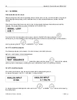
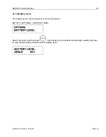
Страница 45: ...A 39 12 1 3 Battery level The battery level of each radio sensor can be monitored SETUP OPTIONS BATTERY LEVEL Select this option and then press Each sensor can be selected individually enabling the us...

Страница 46: ...nsmitting LED on the sensor is blinking Communication error Poor reception Verify which sensor is causing the error by looking at the communication error screen see section 11 Verify that the transmit...

Страница 47: ...e cause is identified 1 Spray Cleaning The enclosures used for the PRS 40 EZ system are water protected to IP 65 This means protection against the environment such as rain However through the use of s...

Страница 48: ...n opening the battery cover and transmitter to avoid damage to the gasket causing moisture ingress which could corrode the batteries and terminals Inspect the gasket surface on the transmitter for nic...

Страница 49: ...91 Power cable Item Part number Qty Description 1 031 300 060 382 1 Console Accy Mounting Arm W 1 Ball 2 031 300 050 485 3 Screw 10 24 X 5 8 Ph Ph 2 031 300 050 487 3 Washer Sealing 10 2 031 300 050 4...

Страница 50: ...e Manual PRS 40 EZ PRS 40 EZ REV A 03 16 06 190201_A 44 14 2 A2B 031 300 060 593 Radio A2B transmitter assembly 031 300 060 586 Antenna only Radio A2B transmitter 031 300 050 688 031 300 050 763 Neopr...

Страница 51: ...Part Numbers PRS 40 EZ REV A 03 16 06 190201_A 45 031 002 060 022 Radio A2B switch 031 300 050 295 A2B Mounting standoff 031 300 050 264 A2B mounting plate 031 300 050 272 Lynch pin...

Страница 52: ...S 40 EZ PRS 40 EZ REV A 03 16 06 190201_A 46 14 3 WIND 031 300 050 321 031 300 050 480 Mounting pole Anemometer mounting plate 031 300 050 322 031 300 060 586 Pin Transmitter 031 300 050 323 031 300 0...

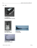
Страница 53: ...Part Numbers PRS 40 EZ REV A 03 16 06 190201_A 47 14 4 ANGLE 031 300 060 695 Sensor Assy Angle w 25 Cable 031 300 060 592 Sensor Angle w Transmitter 031 300 050 577 Plate Radio Angle Mounting...

Страница 54: ...s will interfere with the transmission of the radio signal 031 300 050 672 ANTENNA 918 MHz MAGNETICBASE 13ft LONG WIRE FOR CONSOLE 031 300 050 671 ANTENNA 918 MHz FOR TRS05ASSEMBLY 060 576 WHIP ELEMEN...

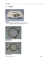
Страница 55: ...PRS 40 EZ REV A 03 16 06 190201_A 49 14 6 LINERIDER Linerider Please contact Hirschmann ECS with questions concerning repair or replacement of component 717 263 7655 031 300 060 434 Extension cable 03...

Страница 56: ...IPPER LENGTH OPTION 3 031 300 100 999 1 00 PIN 1 5 DIAMETER FOR USE W 15T FORCE TRANS OPTION 3 031 300 050 574 1 00 PIN BUSHINGS 1 1 4 FOR 7 5T RADIO LOADCELL OPTION 3 031 300 050 555 1 00 PIN BUSHING...

Страница 57: ...HARDWARE COTTER PIN 3 8 x 3 4 031 300 050 568 1 00 PIN 2 25 FOR 40K RADIO LOADCELL 1 1 8 ROPE OPTION 5 031 300 050 568 1 00 PIN 2 25 FOR 40K RADIO LOADCELL 1 1 8 ROPE OPTION 5 031 300 050 559 1 00 PI...

Отзывы: