Operation Manual
BinTra
c Operator’s Manual Ver. 3.18 Rev. 1.01
11
Part Number MAN-000004-2
Internal Mode
Any changes made to the internal settings may adversely affect how the BinTrac system
operates. DO NOT make changes to any items without understanding the affect it may
have on the operation of the BinTrac System.
Accessing the Internal mode
1. Press and hold the BIN key until
is displayed.
Note:
The display will first
show
- continue holding the BIN key until
is shown.
Segmented display:
Navigating Internal mode
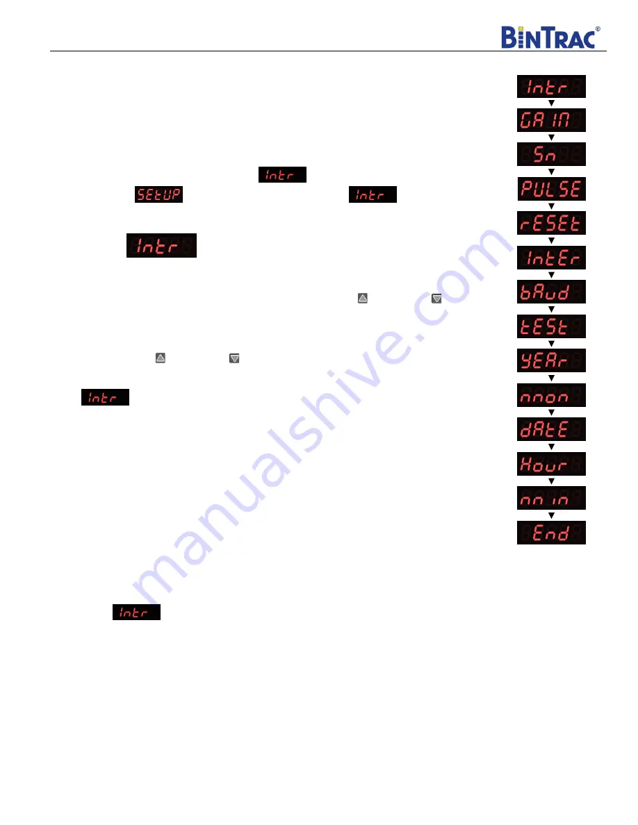
To navigate through the options in Internal mode, use the UPPER
and LOWER
keys to cycle through the options/parameters. See
Figure 3
for the Internal menu flow chart.
Selecting an Option in Internal mode
To select an option/parameter to edit in Internal mode, navigate to the option you wish to
edit using the UPPER
and LOWER
keys and then press the BIN key.
Internal
When
is displayed on the indicator, the following settings can be configured. Set the
Bin LEDS as Flashing (Disabled) or Solid On
(Enabled)
❖
BIN A - Change Single bin weight transmit to multiple bin weight transmit.
❖
BIN B - Configure transmit data to expanded weight data.
❖
BIN C - Totalize Multiple Summing Boxes (V3.03+)
❖
BIN D - Change transmitted weight values from fixed 5 digits to fixed 6 digits.
Totalizing Multiple Bins
For applications which require more than one Smart Summing Box on a bin, you must totalize
the Smart Summing Boxes so they can be displayed on a single indicator. For example, a 15
leg bin would require 15 load cells. As one Smart Summing Box is only capable of handling
8 load cells, you would use a second Smart Summing Box for the other 7 legs of the bin. When
this feature is enabled, the total weight will be displayed under BIN A.
1. Enter Internal Mode.
2. With
displayed on the screen, enable BIN C.
3. Exit Internal Mode
Smart Summing Box Setup
To totalize multiple Smart Summing Boxes, set dipswitches in Smart Summing Boxes as B, C, and/or D. Do NOT set
any as Bin A. When totalizing is enabled, the total will be displayed as Bin A.
BinTrac Indicator Setup
Enable Bins A plus B and C if two Smart Summing Boxes are required, or Bins A plus B, C, and D if three Smart
Summing Boxes are required. Program
“L.C.CAP” parameters for each Smart Summing Box as if it were a single bin.
Be sure to program summing boxes correctly matching the number of load cells on each summing box. Program Bin A
“L.C.CAP” as the total capacity of all connected summing boxes. Program Bin A “Full” as the total amount of feed that
can be stored in the bin.
Figure 3


