background image

4 Planning and installation – Delivery system

56

HDG 

HOSE


JUNCTION

S

COPE


OF


DELIVERY

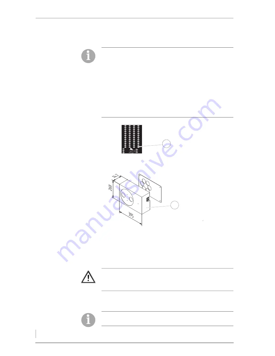
1 Hose junction incl. cover plate

2 Label for inscription

G

ENERAL


INFORMATION

The HDG hose junction can be installed on a wall or free-standing
with the stand.

Using the stand, the hose junction can be installed free-standing in
the room.

L

ABEL

In order to combine several HDG PSS or FRA-PSS pellet delivery sys-
tems on an HDG pellet vacuum container, the HDG hose junction
can be used. It is positioned between the transfer stations of the PSS
augers and pellet vacuum container.

Accordingly, installation of the hose junction is performed after ins-
tallation of the vacuum and return hose on the transfer station of
the PSS auger.

See the operating manual for the HDG pellet delivery system PSS
or FRA-PSS and the HDG pellet vacuum system, chapter 4 "Plan-
ning and Installation", section 4.5 "HDG pellet vacuum system",
paragraph "Installing the vacuum and return hose".

Figure 4/26 - Accessories for delivery system with suction sensors

05/2010

007057/01

1

2

Important!

The hose junction must be installed using the supplied metal do-
wels in such a way as to ensure problem-free access from outside.

The vacuum hoses are labelled A1, A2 or A3, and the return hoses
B1, B2 or B3, depending on the number of pellet augers. 

Содержание Compact 100

Страница 1: ...hdg bavaria com HDG Compact 99 200 Operation Manual ...

Страница 2: ......

Страница 3: ...k side of HDG Compact 99 100 105 115 18 Front side of HDG Compact 150 194 199 200 19 Back side of HDG Compact 150 194 199 200 20 3 2 Functional description 21 Combustion process 21 Delivery system 22 HDG Control 22 Control modes 23 3 3 Technical data 24 3 4 Fuel quality requirements 26 Permissible fuel 26 Wood chips 27 Wood pellets 28 Recommended fuel 29 4 Planning and installation 31 4 1 Planning...

Страница 4: ...y device 61 4 10 Hydraulic system 63 5 Commissioning the system 64 5 1 Requirements 64 5 2 Procedure 65 Switching on the heating system 65 Setting the display language 65 Checking the actuators in manual operation 65 Filling the ash accumulation bin 67 Filling the fuel bunker 68 Adapting parameters 68 6 Using the heating system 69 6 1 Overview of the controls and display components 69 Main switch ...

Страница 5: ...ure control values 94 6 8 TIME menu 94 Procedure 94 Setting the filling ignition and fan activation 95 Setting pre air heating up and burning out 95 Setting the ash removal and ember sustaining functions 95 Setting the cleaning function 96 Setting filling delay of dosage tank 96 Setting filling delay of dosage transition 97 Setting the moving floor delivery system 97 Setting the agitator 98 Settin...

Страница 6: ...ing Profibus DP DDC 116 Entering password 117 Resetting parameters to the factory default 117 6 11 INFO menu 118 6 12 Filling the fuel bunker 118 Requirements 118 Procedure for filling with wood fuel products 119 Procedure for filling of pellets 119 6 13 Performing the chimney sweep test 119 Before the test 120 During the test 120 7 Cleaning and servicing the heating system 122 7 1 Cleaning and ma...

Страница 7: ...nspecting the fuel bunker 146 8 Troubleshooting 147 8 1 Procedure 147 8 2 Possible faults 147 9 Notes on dismantling and disposal 156 9 1 Dismantling 156 9 2 Disposal 157 10 Warranty 158 10 1 Scope 158 10 2 Conditions 158 10 3 Warranty exclusions 158 11 Appendix 159 12 Index 160 ...

Страница 8: ...nformation in this edition was correct at the time of going to press All details in these instructions on standards regulations and works heets should be checked before use and should be compared with the regulations applying locally at the site where the system is ins talled We reserve the right to make changes which may then differ from the technical details and illustrations in this operating m...

Страница 9: ... of the heating system 4 Planning and installation how to properly plan and install the heating system 5 Commissioning the system how the heating system is put into initial service 6 Using the heating system how to properly operate the heating system 7 Cleaning and servicing the heating system how to clean the heating system and who is responsible for its maintenance 8 Troubleshooting how to recti...

Страница 10: ...itch Switches off the mains supply to the entire heating system HDG Compact 99 200 Boiler for burning wood chips shavings and wood pellets HDG Control Electronic control unit of the boiler feeding system and delivery system Heating system Comprised of boiler and corresponding accessories Extinguishing device Extinguishes what is within the delivery system if the temperature of the contents exceeds...

Страница 11: ... systems Any further implementation of applicable stan dards for example with regard to the installation of the heating system pipework etc is not part of this operating manual HDG Ba varia does not assume any liability for this PROPER AND IMPROPER MANNER OF OPERATION PURPOSE OF THE HEATING SYSTEM The HDG Compact 99 200 heating system is designed for the stan dard use of burning wood fuel products...

Страница 12: ...lack of oxygen If the boiler is operating carbon monoxide can be emitted through the cleaning or inspection openings Do not leave these open any longer than necessary Warning Danger of fire Opening doors and lids to hot combustion residues can pose the danger of fires Keep the openings closed during operation and when performing cleaning work allow the combustion residues to cool down before you p...

Страница 13: ...from open cleaning or inspection hatches can cause explosions Do not leave these open any longer than necessary Warning Risk of injury from automatically driven components When working on the automatic ash removal or automatic cleaning systems hands and arms could be injured Turn off the main switch when performing any work on automati cally driven components Danger Dangerous electrical current or...

Страница 14: ...med by a qualified electrician Warning Hazardous area Working in areas marked with this symbol can lead to serious inju ries or to extensive material damage Warning Hand injuries can occur Working in areas marked with this symbol can lead to hand injuries Warning Automatic start up Working in areas marked with this symbol can lead to injuries due to automatic start up Caution Hot surfaces Working ...

Страница 15: ...always be kept readily accessible at the place where heating system is installed Danger Danger of asphyxiation due to lack of oxygen When working in areas marked with this symbol there is a danger of asphyxiation due to high concentrations of carbon monoxide Danger Danger of explosion When working in areas marked with this symbol there is a danger of explosion due to high concentrations of carbon ...

Страница 16: ...tem you can choose between the following TBZ 150 for feeding wood chips planing shavings and pellets Pellet vacuum delivery system with TBZ 80 for feeding the pellets The HDG Compact 99 200 heating system can also be equipped with the following delivery systems Flexi blade delivery system FRA Jointed arm delivery system Walking floor delivery system Silo delivery system Pellet delivery system Rega...

Страница 17: ...oiler supply connection DN 65 5 Lambda sensor 6 Boiler return connection DN 65 7 Fly ash chamber cleaning door 8 Flue pipe connection 9 Fly ash removal auger 10 Combustion fan 11 Combustion chamber ash removal auger 12 Servo motor for secondary air 13 Ignition fan 14 Servo motor for primary air 15 Pressure equalisation hose 16 Feeding system Figure 3 1 Front side of HDG Compact 99 100 105 115 9 8 ...

Страница 18: ...ion sleeve for thermal safety device DN 15 inside thread 2 Safety heat exchanger connections DN 20 outside thread 3 Eyebolt for crane transport 4 Combustion chamber 5 Fill level indicator 6 Stepped grate 7 Ash removal motor 8 Heat exchanger surfaces with cleaning turbulators in between Figure 3 2 Back side of HDG Compact 99 100 105 115 8 7 6 4 5 3 2 1 ...

Страница 19: ...supply connection DN 80 4 Cleaning system drive 5 Flue pipe connection 6 Lambda sensor 7 Boiler return connection DN 80 8 Fly ash removal auger 9 Combustion fan 10 Combustion chamber ash removal auger 11 Servo motor for secondary air 12 Ignition fan 13 Servo motor for primary air 14 Pressure equalisation hose 15 Feeding system Figure 3 3 Front side of HDG Compact 150 194 199 200 9 8 6 5 4 3 2 1 7 ...

Страница 20: ...on sleeve for thermal safety device DN 15 inside thread 2 Safety heat exchanger connections DN 20 outside thread 3 Eyebolt for crane transport 4 Fill level indicator 5 Stepped grate 6 Combustion chamber 7 Ash removal motor 8 Heat exchanger surfaces with cleaning turbulators in between Figure 3 4 Back side of HDG Compact 150 194 199 200 4 4 8 7 6 5 3 2 1 ...

Страница 21: ...t 99 200 heating system the fuel is automati cally fed from the bunker into the combustion chamber of the boiler via the delivery and feeding systems The combustion fan is already activated here in order to eliminate any possible residual combustion gases or negative flue pressure conditions along the combustion path Once the filling cycle is complete the fuel introduced into the com bustion chamb...

Страница 22: ...c ash removal system using delivery augers The air necessary for combustion is supplied as required via two servo motors Via sensors Continuously monitor the firing Adapt boiler output for the heat requirements Minimise emissions and Optimise boiler efficiency DELIVERY SYSTEM The delivery system is in the fuel bunker The fuel is transported from the fuel bunker to the dosing unit or to the interme...

Страница 23: ...ombustion control Constant specified combustion chamber temperature and op timal combustion through modification of primary and secon dary air and fuel quantity No output regulation Preferred method of operation with buffer tank Control of combustion and power Output supplied is adjusted to heat used with optimised com bustion Operation without accumulator Oil burner An oil burner is also fitted t...

Страница 24: ...nimum return temperature 60 C Water capacity 210 l 225 l Weight net 1540 kg 1585 kg Planning data for flue calculation DIN EN 13384 1 Flue gas temperature Tw at Nominal thermal power Minimum thermal power 200 C 140 C Flue gas mass flow at Nominal thermal power Minimum thermal power 0 0610 0 0650kg s 0 0210 0 0200kg s 0 0610 0 0650kg s 0 0210 0 0200kg s 0 0642 0 0673kg s 0 0223 0 0209kg s 0 0681 0 ...

Страница 25: ...capacity 450 l Weight net 2140 kg 2220 kg 2220 kg 2220 kg Planning data for flue calculation DIN EN 13384 1 Flue gas temperature Tw at Nominal thermal power Minimum thermal power 200 C 130 C 200 C 140 C 200 C 150 C 230 C 150 C Flue gas mass flow at Nominal thermal power Minimum thermal power 0 0927 0 0878kg s 0 0338 0 0294kg s 0 1060kg s 0 0370kg s 0 1290kg s 0 0460kg s 0 1180 0 1060kg s 0 0440 0 ...

Страница 26: ...nic ha logen compounds or containing heavy metals FUEL CLASS 7 Plywood chipboard fibreboard or otherwise glued wood including remains thereof provided no wood protection agents have been ap plied or are present as the result of a treatment and coatings do not contain organic halogen compounds or heavy metals Fuel classes 6 or 7 may only be used in a wood processing plant at 30 kW or more nominal t...

Страница 27: ...allowed The numeric value of the P class refers to the size of the wood chips in mm which fit through a round opening with the indicated sieve opening size The cross section of the outsized particles must be smaller than 2 cm 2 P45 Medium wood chips with a particle size of up to 45 mm P45 are used in larger systems but can however depending on the diameter of the conveyor auger also still be suita...

Страница 28: ... from the wood processing industry as well as unprocessed forestry waste They have a standardised dia meter and length They are pressed at a very high pressure and have a very low water content The energy contained in 2 kg of pellets cor responds approximately to the energy contained in a litre of heating oil In accordance with DIN EN 14961 2 the fuel specifications for wood pellets are separated ...

Страница 29: ...uel the higher the thermal value and the better the burning that is achieved High quality fuel aids in energy conservation and maintains the operating safety of your heating system The optimal ash content is 1 by weight A1 0 For HDG Compact 99 200 heating systems it is possible to use wood fuel products of grain size P45 with a maximum water content of up to 30 However reduced nominal thermal powe...

Страница 30: ...ar attention to the fuel quality both when ordering and during the delivery Important If there is a significant change of fuel the system must be reset ac cordingly and checked for emissions by authorised specialists Wood chips P45 M20 A1 0 A1 5 or Pellets A1 A2 Wood chips P45 M25 A1 0 A1 5 Wood chips P45 M30 A1 0 A1 5 Shaving briquettes A1 A2 D60 L50 Planing saw shavings A1 A2 M20 A1 0 A1 5 HDG C...

Страница 31: ...m REQUIRED ROOM SIZES AND MINIMUM SPACING Minimum ceiling height 2250 mm optimal ceiling height 2500 2750 mm Figure 4 1 Necessary room sizes and minimum spacing E F D B C A A B C D E F HDG Compact 99 100 105 115 2280 3500 813 280 330 1000 HDG Compact 150 194 199 200 2400 4650 935 280 330 1000 Table 4 1 Minimum size mm ...

Страница 32: ...ensure unhindered operation and maintenance of the heating system you must ensure that the heating system is installed to our specifications and that the minimum spacings are maintained Also note that the thresholds in DIN 4109 Soundproofing in building construction may not be exceeded More detailed information can be found in the respective ordinances of the German states We recommend that object...

Страница 33: ...eriod is desirable PASSAGE THROUGH THE WALL The passage through the wall normally has to be made in the wall between the heating room and the fuel bunker Its position depends on the distance and the position of the HDG Compact heating system within the room and the customer s installation diagram The passage through the wall between the heating room and the fuel bunker should have a width of 70 cm...

Страница 34: ...y version 1 Dosage directly to TBZ 1 Dosage 2 Feeding system Delivery version 2 Dosage conveyor auger to TBZ 1 Dosage system II motor of delivery system runs along with do sage system 2 Dosage 3 Feeding system Figure 4 2 Delivery system version 1 1 2 Figure 4 3 Delivery system version 2 1 3 2 ...

Страница 35: ...ivery 1 Delivery system 2 Dosage 3 Feeding system 4 Fill level indicator Delivery version 4 sloping auger delivery silo delivery system 1 Delivery system 2 Fill level indicator 3 Dosage 4 Feeding system Figure 4 4 Delivery system version 3 1 4 3 2 Figure 4 5 Delivery system version 4 4 3 2 1 ...

Страница 36: ...ing system and chimney form a single functional unit and must be adapted to one another in order to guarantee fault free and economical operation Figure 4 6 Delivery system version 5 6 5 4 3 2 1 According to EN 303 5 the entire flue system must be installed in such a way that contamination condensation and insufficient flue draught are avoided Here it is to be noted that in the accessible operatio...

Страница 37: ...di mensioned in accordance with DIN EN 13384 1 taking into account the fuel planned and the expected load and which meets local buil ding regulations for the installation site A chimney can only be designed with full knowledge of the on site conditions This includes taking into account the following factors Location of the house Surrounding hills slopes Wind direction Location of the chimney in th...

Страница 38: ...dius of the elbow may not be less than the diameter of the pipe The chimney should be vertical and straight if possible without kinks take particular care in older buildings All of the cleaning and measurement hatches on the chimney must be tightly sealed To reduce the entry of additional cold air only attach one heat ge nerator per chimney To prevent dust from escaping the flue pipe must be seale...

Страница 39: ...atic ignition It is however highly recommended to use an accumulator even with automatic boiler systems The size of the accumulator will depend on the nominal thermal power of the boiler and on the thermal requirements of the building As a benchmark value 20 litres per kilowatt boiler power can be used This results in a boiler burning duration of approximately one hour at full capacity operation d...

Страница 40: ...l data The return temperature is regulated by the HDG control unit The return temperature control consists of a 3 way mixing valve with a 230 V servo drive running time 120 140 s and a circulation pump from energy efficiency class A We recommend for the HDG Compact 99 100 105 115 Wilo 30 1 8 3 way mixer DN 40 or comparable HDG Compact 150 194 199 200 Wilo 50 1 9 3 way mixer DN 65 flange or compara...

Страница 41: ...ue pipe connection Ø 250 mm 3 Boiler supply connection DN 65 flange 4 Filling draining connection DN 15 inside thread Figure 4 8 Dimensions of the flue pipe side of the HDG Compact 99 115 A C F G H B D E 3 2 1 4 A B C D E F G H HDG Compact 99 115 640 390 140 104 1420 1250 464 124 Table 4 3 Dimensions of the flue pipe side of HDG Compact 99 115 mm ...

Страница 42: ...for thermal safety device DN 15 inside thread 2 Safety heat exchanger inlet DN 20 inside thread 3 Safety heat exchanger outlet DN 20 inside thread Figure 4 9 Dimensions of the back side of HDG Compact 99 115 A B C 1 2 3 A B C HDG Compact 99 115 666 1374 1304 Table 4 4 Dimensions of the flue pipe side of HDG Compact 100 105 mm ...

Страница 43: ...onnection Ø 300 mm 2 Filling draining connection DN 25 inside thread 3 Boiler supply connection DN 80 flange Figure 4 10 Dimensions of the flue pipe side of the HDG Compact 150 200 A B C E D 3 2 1 Model A B C D E Compact 150 200 440 190 1250 184 124 Table 4 5 Dimensions of the flue pipe side of HDG Compact 150 200 mm ...

Страница 44: ... sleeve for thermal safety device DN 15 inside thread 3 Safety heat exchanger inlet DN 20 inside thread 4 Safety heat exchanger outlet DN 20 inside thread Figure 4 11 Dimensions of the back side of HDG Compact 150 200 A B C D E 1 2 3 4 Model A B C D E Compact 150 200 1100 1014 1650 1374 1304 Table 4 6 Dimensions of the flue pipe side of HDG Compact 150 200 mm ...

Страница 45: ...omer specific Cleaning tools Operating documentation Upon delivery check that the scope of delivery matches the informa tion on the delivery note The heating system HDG Compact 99 200 1 is delivered on two rectangular wooden planks 2 These wooden planks are intended only for transportation and should be removed before installing the system in its planned location Figure 4 12 HDG Compact 100 boiler...

Страница 46: ...alists to perform the installation Danger Dangerous electrical current or voltage Working on live components can result in an electric shock Switch off the mains supply to the heating system during the instal lation Important When laying the pipelines observe the minimum required clea rances See section 4 1 Planning the heating system in this chapter Important Due to the noise we recommend acousti...

Страница 47: ... included in the scope of delivery so that it is horizontal 4 Unscrew the ring bolt from the boiler The boiler has been set up INSTALLING THE FEEDING SYSTEM ATTACHING THE ADAPTER PIPE 1 Slide the adapter pipe 1 with the seal 3 into the feed channel 4 2 Align the seal 3 with the holes 3 Poke a hole through the seal 3 for the centring screw 2 Warning Danger from suspended loads The boiler weighs ove...

Страница 48: ...screws 2 from the boiler through the holes 6 Insert the second seal 1 on the adapter pipe 4 7 Slide the feeding system 3 onto the adapter pipe 4 8 Bolt on the feeding system 3 with the M12 nuts using an SW19 spanner Warning Danger of injury The feeding system is very heavy Hands and feet could be crushed when it is lifted Only lift the feed system using suitable lifting equipment Figure 4 14 Attac...

Страница 49: ... on the connections of the pressure equalisa tion hose 2 2 Attach the union nuts DN 32 to the feed system 1 and the boiler 3 The pressure equalisation hose is connected 3 Remove the servo motor cover 4 9 Bolt the support leg 3 with an M12 screw 2 onto the fee ding system 1 using an SW19 spanner 10 Fix the support leg 3 to the floor as required screws and screw anchors are not in cluded in the scop...

Страница 50: ...ING ASH CONTAINER S ASH CONTAINER 80 L 1 Remove the ash containers from the packaging 2 Lift up the two clamp handles 1 3 3 Insert the ash containers 2 on the ash removal pipe 4 Press the clamp handles downward Grasp the clamp handles and press the ash containers against the seal of the ash removal door 5 If the clamp handles do not clamp adjust them as follows Figure 4 17 Setting the pressure equ...

Страница 51: ...djust the ash container with the interior nuts 1 until the clamping handles latch firmly 4 Screw on the nuts and check that the clamp handles clamp firmly Figure 4 19 Adjusting the ash containers 1 Optionally for the HDG Compact 99 200 heating system 140 l ash containers can be installed instead of 80 l ash containers Installation and adjustment is performed in the same way as with the 80 l ash co...

Страница 52: ... the ash accumulation bins 3 4 4 Install the torque support 2 using the M10 hexagon socket screws spanner size SW6 on the ash accumulation bin 3 5 Install the auger trough 5 using the M8 hexagon socket screws spanner size SW5 on the torque support 2 6 Push the ash removal auger 6 through the auger trough 5 Figure 4 21 Removing clamping devices 1 Figure 4 22 Pre assembling the central ash removal s...

Страница 53: ...ins 4 on the ash removal doors 1 with the M12 screws and nuts spanner size SW19 and washers 10 If necessary compensate for any unevenness on the floor with the aid of the adjustable legs 3 on the ash accumulation bins 4 11 Tighten all the screws on the central ash removal system 12 Insert the feather key 2 into the ash removal auger Figure 4 23 Installing the ash accumulation bins 2 4 1 3 Figure 4...

Страница 54: ...ng after a cleaning there is a danger of back firing or smoke from the boiler This can cause damage to the heating system or injury to persons Make sure that both ash accumulation bins 1 are at least half filled with ash sand etc The sensors for the buffer tank are in the EMD C 215 Exclusiv control cabinet for further use 1 Seal the immersion sleeves of the sensors with a suitable sealing material...

Страница 55: ...he control panel of HDG Control Install the control cabinet at a height comfortable for you to ope rate CONNECTING THE CHIMNEY See section 4 2 Connections in this chapter 1 Connect the flue pipe to the chimney connection or with the HDG cyclone dust extractor 2 Make sure that the connecting piece does not protrude into the chimney 3 Seal the connection to the chimney with highly fireproof silicone...

Страница 56: ...t vacuum container Accordingly installation of the hose junction is performed after ins tallation of the vacuum and return hose on the transfer station of the PSS auger See the operating manual for the HDG pellet delivery system PSS or FRA PSS and the HDG pellet vacuum system chapter 4 Plan ning and Installation section 4 5 HDG pellet vacuum system paragraph Installing the vacuum and return hose F...

Страница 57: ... the hose end 3 Label the hose end with the provided A1 label 1 4 Insert the hose end through the A1 opening in the cover plate 3 until the outside of the hose is flush with the wall 5 Proceed with hoses A2 A3 or B1 B2 B3 exactly as described above Figure 4 27 Wall penetration for hose junction Figure 4 28 Cutting and laying hose 2 3 1 Important Observe the minimum bending radius of 30 cm For easi...

Страница 58: ...lamps 11 Mount the hose junction 4 on the wall 12 Dismantle the cover plate 1 in the storage room 13 Fill the wall penetration with mineral wool 2 14 Mount the cover plate 3 on the wall Figure 4 29 Installing hose on hose junction Fig 1 10 Schlauchklemmen aufstecken Fig 1 11 Schläuche mit Schlauchklemmen be gen 3 1 2 4 Important The earthing leads in the hoses must be in contact with the connec ti...

Страница 59: ...d at the hose end ca 5 cm 17 Bend the earthing lead inward 18 Label both hoses with the provided A and B labels 19 Place the hose clamps on the hose junction connections 20 Place the labelled hoses 1 on the hose junction connections 21 Secure the hoses 1 with the aid of the hose clamps 22 Replace the cover 2 on the hose junction The HDG hose junction is now installed Figure 4 31 Vacuum and return ...

Страница 60: ...oad capacity of the system See the HDG underpressure control manual 4 7 Electrical system The electrical connections must be made in accordance with DIN IEC 60364 Setting up low voltage electrical installations The technical details are described in the chapter 3 Mode of ope ration section 3 3 Technical data 1 Install the electrical connections in accordance with the provided circuit diagrams The ...

Страница 61: ...d water flows through the safety heat ex changer The excess energy generated is thus dissipated by the emergency cooling This is an alternative to fast regulation However the safety heat exchanger and thermal safety device can only serve their purpose if the following requirements have been met A flow pressure of at least two bar and a flow rate of 1800 l h must be available at the cold water inle...

Страница 62: ... Safety heat exchanger connections DN 20 inside thread HDG COMPACT 150 200 1 Connection of immersion sleeve for thermal safety device DN 15 female 2 Safety heat exchanger connections DN 20 inside thread Figure 4 33 Installing the HDG Compact 99 115 thermal safety device 1 2 Figure 4 34 Installing the HDG Compact 150 200 thermal safety device 1 2 ...

Страница 63: ...Supply temperature sensor boi ler temperature RT Return temperature sensor At Acc top Ab Acc bottom The hydraulic system is only suitable for the indicated purpose and in the specified manner Any deviation from this usage could make adjustments necessary Consult with a trained specialist on issues relating to the hydraulic system ...

Страница 64: ...ker of the mains supply to the heating system switched off CHECK THE MECHANICAL STRUCTURE OF THE FEEDING SYSTEM Does the mechanical structure meet the specifications of this ope rating manual CHECK THE HYDRAULIC CONNECTIONS Do the mechanical connections meet the specifications of this operating manual Has the safety equipment been installed to conform to the appli cable standards and guidelines CH...

Страница 65: ...ystem main switch on The control is activated After a start up phase the display will first of all show a switch on message and then the standard display 2 Set the engage switch to 1 The display switches to Heating ON The heating system is now switched on SETTING THE DISPLAY LANGUAGE Different languages can be set for the display texts See the chapter entitled 6 Using the heating system section 6 ...

Страница 66: ...6 Using the heating system section 6 9 MANUAL menu paragraph Feeding and dosage FEEDING METERING AND EXTRACTION In this submenu the feeding and the delivery system can optionally be activated together with the dosing auger lying in between See chapter 6 Using the heating system section 6 9 MANUAL menu paragraph Feeding dosage and delivery system FEEDING METERING VACUUM FAN AND DELIVERY SYSTEM In t...

Страница 67: ...manual ope ration the HDG Compact 99 200 heating system can be operated in accordance with the set control mode FILLING THE ASH ACCUMULATION BIN 1 When commissioning the system make sure that both ash accu mulation bins 1 are at least half filled with ash sand etc The following section is only relevant when operating theHDG Compact 99 200 heating system with a central ash removal system Caution Ma...

Страница 68: ...heating fuel If the heating system is operated with wood pellets or chips the relevant parameters must be changed In all cases it is necessary to check the predefined parameters and if necessary change them accordingly before commissioning the system The fuel bunker may only be filled once the actuators have been tested Warning Damage to delivery system during filling If the heating system is not ...

Страница 69: ...ng system are switched off If the emergency stop switch is pulled out the Acknowledge fault button must first be pressed Only then will all moving parts of the heating system be switched back on and operational ADDITIONAL CONTROLS Engage switch switches the heating system on or off System operation indicator light lights up when the heating system is switched on Acknowledge fault key flashes when ...

Страница 70: ...Bavaria GmbH 07 2008 CONTROL CABINET MODEL EMD C 215 EXCLUSIV 1 Lock mechanism of control cabinet 2 Main switch 3 Emergency stop 4 Acknowledge fault button with fault light 5 System operation indicator light 6 Engage switch 7 HDG Control control unit Figure 6 1 Control cabinet model EMD C 215 Exclusiv 1 3 2 7 6 4 5 ...

Страница 71: ...on 6 Up arrow button 7 Configuration button 8 No function assigned 9 Numerical keypad 10 Enter or Input button 11 Function buttons F1 to F6 12 CE button The control unit of the HDG Control is located in the front plate of the control cabinet Through the control unit you can adjust the HDG Control and obtain information on current processes DISPLAY The display shows the selected information and par...

Страница 72: ...t any submenu and return to the stan dard display Keys of the numerical keypad The keys of the numerical keypad are used to enter settings and times Enter or Input key Confirms the changed value One step forwards Configuration button If the HDG Control is traded the configuration key is used to con firm adoption of the previous hours of operation 6 2 Switching on the heating system REQUIREMENTS Be...

Страница 73: ...d off from any operating mode 1 Set the engage switch to 0 The heating system is switched off the supplying of fuel is stopped the combustion air fan continues running for a preset burn out time 2 Allow the heating system to burn out until the combustion air fan switches off 3 Turn the heating system main switch off No operating mode is displayed on the control unit of the HDG Control The heating ...

Страница 74: ...e in the combustion chamber have been reached Automatic control Only for Combustion control or Combustion and output con trol mode The heating system runs automatically according to the configu red control mode Autom uncontrolled Operation of the heating system in Fixed value mode Burn out phase The preset boiler temperature has been reached The boiler has been switched off This operating status i...

Страница 75: ...e heating system is controlled via an external heating circuit regulator There was no enable command from the superordinate heating circuit regulator Lambda stop The residual oxygen value for combustion has fallen below the minimum The heating system waits until the minimum residual oxygen value has been reached again Material stop The fill level indicator in the combustion chamber has signalled T...

Страница 76: ...am COMP_12a 15 12 11 Program file Program date 15 12 11 Doebereiner Program update Language selection 1 13 Language 1 German FIELD CHOOSE END By pressing the F6 key under the END command you can exit the Language selection menu window without changing the set ting The following pages show all practically available menu windows In actuality only those menu windows are available to the operator whic...

Страница 77: ...LER This menu can be used to integrate an additional peak load boiler using a third accumulator temperature sensor With a double hea ting system both boilers store energy in the accumulator If the base load boiler cannot charge the accumulator by itself the peak load boiler switches on for support This menu allows you to configure which heating system will be the base load boiler and the which wil...

Страница 78: ...eeds 200 C This means that Boiler 1 must receive demand signals from the accumulator sensor and Boiler 2 must receive the external demand signal from Boiler 1 SETTING OPERATING TIMES In this menu you can view and set the operating times of the heating system There are two switch on and switch off cycles available per weekday BOILER OPERATING TIMES See Procedure in this section 1 In the Show switch...

Страница 79: ... restored PELLET HOPPER OPERATING TIMES 1 Press the F1 key under the standard display screen You are in the ON OFF menu 2 Scroll with the F2 key to the submenu Switch on off time Hopper 1 04 The first switch on time is shown in black 3 Set the times using the numerical keypad 4 Confirm each change with the Enter key The cursor moves to the next digit pair 5 Press the F6 key under the END command t...

Страница 80: ... and output In addition to the combustion control this version also regu lates the output of the heating system for the demand Oil burner In this version an oil burner must be installed in the boiler This control mode switches off all units except the return pump and return mixing valve If the regulating thermostat on the boiler has enabled this the oil burner and the return mixing valve re gulate...

Страница 81: ...on the heating system is switched on and off if the accumulator temperature sensor has enabled this or there is a simultaneous external demand On In this version the heating system is switched on and off through the boiler supply temperature sensor The accumu lator temperature sensors are ignored Thermostat In this version the heating system is switched off through the boiler supply temperature se...

Страница 82: ...ing of the minimum lambda value see section 6 7 C QUANTITY menu paragraph Entering the residual oxygen set ting ADJUSTING THE ASH REMOVAL SETTING The movement of the stepping grate and the ash removal system can be switched off See Procedure in this section CHANGING THE CLEANING SYSTEM SETTING The automatic heat exchanger cleaning system can be switched off See Procedure in this section Setting 1 ...

Страница 83: ... After the heating up phase it switches off 3 Automatic Depending on the local site conditions and fuel characteristics this mode may be required as a flue support to stabilise opera tion The fan starts and continues running through the opera ting mode Automatic Afterwards it switches off 4 During combustion In this mode the fan is in operation if the combustion fan of the heating system is runnin...

Страница 84: ...8 TIME menu in this chapter Continuous running In this version the extraction runs continuously upon demand See Procedure in this section MODIFYING THE PELLET VACUUM DELIVERY SYSTEM SETTING Optionally the heating system can also be operated with a pellet va cuum delivery system 1 Suction point In this variant the pellet vacuum delivery system is operated without hose junction 2 3 Suction points In...

Страница 85: ... are switched off Auto scraper 1 In this version only scraper 1 of the moving floor is controlled Auto scraper 2 In this version only scraper 2 of the moving floor is controlled Auto scraper 1 2 In this version both scraper blades of the moving floor are al ternately controlled Manual mode In this version the moving floor scrapers can be controlled by hand The manual control function in the Manual...

Страница 86: ...revious or next submenu The first resettable parameter is shown in black 3 Enter the desired value using the numerical keypad 4 Confirm each change with the Enter key The desired parameter is set 5 Scroll with the Up or Down key to the previous or next submenu The next resettable parameter is shown in black 6 Repeat steps 3 to 5 for additional parameters 7 Press the F6 key under the END command to...

Страница 87: ...is section C Quantity 2 02 Boiler temp 80 60 C Return temp 60 50 C Comb chamber temp 600 331 C Residual oxygen 8 0 8 6 END The Boiler temperature target value must not fall below 70 C and must not exceed 85 C The Return temperature target value must not fall below 60 C Comb chamber temp and Re sidual oxygen cannot be changed Values from controller 2 03 Material quantity 50 0 40 0 Material differen...

Страница 88: ... by adapting the tempera ture Temp acc top below If this temperature set for the top accumulator sensor is not met the boiler switches back on Temp acc bottom above If the temperature set for the bottom accumulator sensor is ex ceeded the boiler switches off In this menu the settings of the fuel and air quantities are fixed value presets for Fixed value operation only See section 6 6 ON OFF menu u...

Страница 89: ...or sensor is ex ceeded the peak load boiler switches off See Procedure in this section Temperature adjustment using the accumulator sensors is only available if the boiler activation is set to Accumulator temperature sensor See section 6 6 ON OFF menu under Selecting and setting boiler activation Boiler on off 2 06 On Temp acc top below 70 58 C Off Temp acc bottom above 65 51 C END The standard se...

Страница 90: ...ature range for operation with combustion and output control MAX The boiler attempts to reach this maximum temperature at full load MIN This minimum temperature is the lower limit for partial load operation of the boiler See Procedure in this section This is an optional submenu and only available with double heating systems if necessary also with oil gas boilers Peak load boiler 2 08 Monitoring of...

Страница 91: ... 600 C and MIN 400 C The material settings apply for Combustion control as well as Combustion and output control See section 6 6 ON OFF menu under Setting the control boiler activation ignition and Lambda Stop Material quantity PID 2 6 02 MAX 28 0 CCT_SET 600 C KP 5 00 MIN 15 0 CCT_ACT 50 C TN 100 00 TV 0 00 SET 15 0 Factor 50 KP_ 17 90 END The difference between fuel quantity MAX and MIN should b...

Страница 92: ...ection The difference between primary air quantity Air_Max and Air_Min should be specified as a range adapting to the required value approx 25 The residual oxygen setting applies for Combustion control as well as Combustion and output control See section 6 6 ON OFF menu under Setting the control boiler activation ignition and Lambda Stop O2 preset value R 2 6 04 O2_MAX 8 0 CCT_SET 600 C O2_MIN 8 0...

Страница 93: ...or the secondary air is 100 for Max and 20 for Min If this O2 minimum value is not met the Lambda Stop function is triggered See section 6 6 ON OFF menu under Activating the function Lambda Stop The material quantity O2 settings apply for Combustion con trol as well as Combustion and output control See section 6 6 ON OFF menu under Setting the control boiler activation ignition and Lambda Stop Fue...

Страница 94: ...E 1 Press the F3 key under the standard display screen You are in the Time menu 2 Scroll with the F1 or F2 key to the previous or next submenu The first resettable parameter is shown in black 3 Enter the desired value using the numerical keypad 4 Confirm each change with the Enter key The desired parameter is set 5 Scroll with the Up or Down key to the next submenu The next resettable parameter is...

Страница 95: ...and the burn out time during which material feeding is stopped and the combustion fan switches off after a specified time See Procedure in this section SETTING THE ASH REMOVAL AND EMBER SUSTAINING FUNCTIONS This submenu is used to set the time for the grate motion and thus the de ashing interval In addition the time interval for the material feeding can be influenced if the Ignition parameter is s...

Страница 96: ...pause time 10 0 0 0 m END When changing the heating material the burn out behaviour must be checked on the grate of the boiler If necessary adjust the Ash removal pause parameter In general only this parameter should be changed and the Ash removal feed parameter only changed in exceptional instances Time 3 04 Cleaning system pause time 24 0 0 0 h Cleaning system runtime 140 0 m Cleaning system mon...

Страница 97: ...is section SETTING THE MOVING FLOOR DELIVERY SYSTEM In this submenu you can enter settings for a moving floor delivery system See Procedure in this section Time 3 05 Delay filling Dosage tank TFD 160 3 0 0 0 m END This is an optional submenu and only available for heating systems with dosage transition and fill level indicator Time 3 06 Delay filling Dosage transition 3 0 0 0 s END This parameter ...

Страница 98: ...E CYCLES OF THE PELLET AUGER In this submenu you can set the time interval for a timed cycle of the pellet auger See Procedure in this section This is an optional submenu and only available with moving floor delivery systems and double heating systems Agitator 3 08 Agitator lag time 2 0 0 0 s END This is an optional submenu and only available with peak load boi lers Time 3 09 Peak load boiler Dela...

Страница 99: ...tings for a hopper ext raction system See Procedure in this section Time 3 10 Delivery system runtime 2 0 0 0 s Delivery system pause time 4 0 0 0 s END This is an optional submenu and only available with hopper extrac tion systems Pellet hopper 3 11 Vacuum fan lead time 10 0 s Vacuum fan lag time 10 10 s Delay fill level indicator 60 60 s Start filling hopper in 30 1 0 m END This is an optional s...

Страница 100: ...n the set runtime of the ash removal auger is exceeded the fault message Ash box full appears The heating system shuts off at this fault The 0 setting deactivates this function WA Lubricate screw stoker When the set runtime of the screw stoker is exceeded the war ning Please lubricate screw stoker appears The heating system does not shut off at the appearance of this warning The 0 setting deactiva...

Страница 101: ...is set time is exceeded during a burning process the boiler burns out and a main cleaning is carried out The system then re starts The 0 setting deactivates this function Cleaning time Setting the runtime of the grate cleaning The 0 setting deac tivates this function See Procedure in this section SETTING THE DAY DATE AND TIME In this submenu you can enter the current day date and time See Procedur...

Страница 102: ...rd display is restored 6 9 MANUAL menu This menu can be used to functionally test all actuators such as drive motors fans and electrical mounted parts PROCEDURE 1 Press the F4 key under the display of the standard display screen You are in the MANUAL menu 2 Scroll with the F1 or F2 key to the previous or next submenu 3 Use the F3 key under the FIELD command in the respective sub menu to select the...

Страница 103: ... grate with the ash removal auger main cleaning dust removal and cleaning system can be activated manu ally See Procedure in this section RETURN PUMP AND RETURN MIXING VALVE This submenu is used to activate the return pump and return mixing valve See Procedure in this section Manual 4 01 Comb air fan Ignition fan FIELD ON END Manual 4 02 Grate ash removal Dust removal Cleaning system Main cleaning...

Страница 104: ...gether with the dosing auger lying in between See Procedure in this section Manual 4 04 Feeding system Dosage FIELD FOR WARD BACK END Danger Material damage and injury due to incorrect operation Activation of the BACK parameter is only possible during feeding and may only be used for short cycles of max 3 seconds Manual 4 05 Feeding system Dosage Delivery system FIELD FOR WARD BACK END Danger Mate...

Страница 105: ...et auger See Procedure in this section FEEDING METERING AND LATERAL AUGER In this submenu if there is a walking floor delivery system the fee ding and the transverse auger can optionally be activated together with the dosing auger lying in between Manual 4 06 Feeding Filling container Dosage Vacuum fan Delivery system FIELD FOR WARD BACK END Danger Material damage and injury due to incorrect opera...

Страница 106: ... the standard display screen You are in the SERVICE menu Manual 4 08 Feeding Dosage Lateral auger FIELD FOR WARD BACK END Danger Material damage and injury due to incorrect operation Activation of the BACK parameter is only possible during feeding and may only be used for short cycles of max 3 seconds Manual 4 09 Hydraulic moving floor Cylinder 1 moving floor Cylinder 2 moving floor FIELD ON END I...

Страница 107: ...enu Service 5 04 4 Scroll with the F1 or F2 key to the previous or next submenu The first resettable parameter is shown in black 5 Enter the desired value using the numerical keypad 6 Confirm each change with the Enter key The desired parameter is set 7 Scroll with the Up or Down key to the next submenu The next resettable parameter is shown in black 8 Repeat steps 5 to 7 for additional parameters...

Страница 108: ...key to start the chimney sweep test The chimney sweep test is carried out OPERATING HOURS COUNTER Various operating hours are displayed Pressing the RESET key for more than 3 seconds resets all operating hours See Procedure in this section When operating the heating system without an accumulator the chimney sweep test can also be carried out in partial load mode with 30 of the nominal thermal powe...

Страница 109: ...unt of time Reverse moving runtime The running time of the reversal in which the feed system runs backwards can also be corrected This value is limited to a ma ximum of three seconds Reverse moving attempts The maximum number of possible reverse attempts can be set Ignition temperature If the temperature in the hot combustion chamber exceeds this value the HDG Control does not switch on the igniti...

Страница 110: ...mber temperature stop After the set temperature is exceeded the heating system swit ches to the operating state Combustion chamber temperature stop See Procedure in this section MODIFYING THE DOSAGE PAUSE MIN OR IMPULSE MIN AND FEED SYSTEM LAG TIME OR FEED SYSTEM LEAD TIME PARAMETERS Dosage pause min and dosage impulse min These parameters are used to set the minimum pause intervals and running ti...

Страница 111: ...an heating See Procedure in this section FUEL QUANTITY 1ST MODIFYING FILLING AND AIR START SETTING Fuel quantity 1st filling Change the fuel quantity of the first filling in heating up mode Air start setting These parameters determine the air quantity of the primary air and secondary air for heating up mode See Procedure in this section Service 5 07 Dosage pause_min 5 0 1 5 s Dosage impulse_min 5 ...

Страница 112: ...Simultaneously press the keys F3 F4 and F5 under the display Service 5 10 Ash removal system minimum pause 25 0 m END Entering the value 100 opens the motors fully 0 closes them fully After exiting this submenu all settings are reset to their ori ginal value Service 5 11 Primary air servo motor 28 28 Secondary air servo motor 63 63 END During the test procedure do not close this submenu Duration a...

Страница 113: ...ccessfully completed The testing of the lambda sensor is completed 5 Press the F6 key under the END command to exit the Service 5 12 submenu The standard display is restored FLUE GAS TEMPERATURE Cleaning system start When this set temperature is exceeded the cleaning system starts up Max flue gas temperature When this set temperature is exceeded the fault message Flue gas temperature too high appe...

Страница 114: ...rpressure control is deactivated parameter 1 08 the flue gas fan runs at the set speed See Procedure in this section SETTING CHIMNEY SWEEP TEST Enabling boiler temperature After this set boiler temperature is exceeded the chimney sweep test is enabled Enabling combustion chamber temperature After this set combustion chamber temperature is exceeded the chimney sweep test is enabled Flue gas tempera...

Страница 115: ... for the chimney sweep test in partial load 30 and nominal load 100 can be set See Procedure in this section SETTING INTERFACE RS485 Interface RS485 Setting options without interface Modbus RTU web server Modbus RTU DDC Profibus DP DDC See Procedure in this section Chimney sweep test 5 15 Enabling boiler temperature 70 60 C Enabling combustion room temp 450 328 C Boiler temp Set 30 100 85 85 C Set...

Страница 116: ...C for a Modbus network Modbus rights Setting of the minimum required rights or enabling of only cer tain PLC parameters in a Modbus network See Procedure in this section SETTING PROFIBUS DP DDC Profibus address Setting of PLC address for a Profibus network Profibus rights Setting of the minimum required rights or enabling of only cer tain PLC parameters in a Profibus network Modbus RTU setting web...

Страница 117: ...s function See Procedure in this section RESETTING PARAMETERS TO THE FACTORY DEFAULT See Procedure in this section The Operating hours parameter is shown in black and the hours of operation can be read 6 Press the F4 and F5 keys to adopt the factory settings The factory settings are adopted Setting Profibus DP DDC 5 19 Profibus address Address 1 Profibus rights 3 HDG FIELD END Service 5 20 Enter p...

Страница 118: ...Press the F4 or F3 key to switch between the most recent fault and the archived faults 4 In the fault archive press the F5 key under the RESET command to delete the fault 5 Press the F6 key under the END command to exit the Fault in formation menu The standard display is restored 6 12 Filling the fuel bunker REQUIREMENTS The following requirements must be met before the fuel bunker can be filled T...

Страница 119: ...eating system in this chapter The filling of the pellet bunker is completed 6 13 Performing the chimney sweep test In Germany there is a legal requirement 1 BImschV that heating systems with nominal thermal power in excess of 4 kW be inspected annually by a qualified combustion engineer to see that federal emis sion limits for small and medium sized boiler systems are met INITIAL INSPECTION The op...

Страница 120: ...t the chimney sweep test Make sure that there is sufficient fuel in the fuel bunker to avoid in terruption of material feeding during the measurement No fault should be present in the system 1 Press the F5 key under the standard display screen You are in the Service menu Warning Material damage and injury due to incorrect chimney sweep test The chimney sweep test requires comprehensive technical k...

Страница 121: ...y Once the specified temperatures have been reached the display shows the Measurement enabled message The measurement is carried out Service 5 01 Digital inputs 0 15 00000000 00000000 Digital outputs 0 15 00000001 00000000 END Chimney sweep test 5 02 Heating OFF Enabling boiler temperature 60 C Enabling comb chamber temp 325 C Measurement time 75 0 m 30 100 END When operating the heating system wi...

Страница 122: ...r specialist heating company The specified maintenance intervals are guidelines Depending on the quality of the fuel and the power used by the heating system more frequent on off operation the intervals may vary Interval Component See page Weekly as required Checking and cleaning the stepped grate Check and empty the ash container Lubricate the feeding system every 150 opera ting hours 124 125 128...

Страница 123: ... start with the cleaning and maintenance work when the surfaces have cooled down Warning Risk of injury from automatically driven components If the heating system is switched on automatically driven compo nents can unexpectedly start running Limbs or fingers could be come caught and crushed Switch the heating system off before performing any cleaning or maintenance work on automatically driven com...

Страница 124: ...bustion chamber door 1 4 Inspect the grate 2 for encrustations of cinder or foreign bodies 5 Remove any encrustations if necessary with a suitable cleaning instrument 6 After cleaning close the combustion chamber door 1 7 Switch the heating system back on See the chapter entitled 6 Using the heating system section 6 2 Switching on the heating system The cleaning of the stepping grate is completed ...

Страница 125: ...tem 2 Allow the fire in the heating system to burn out and cool down 3 Open the ash door 3 4 Lift up the lid 1 and remove it 5 Check the fill level of the ash containers 2 If the ash containers 2 are full empty them Important See Generally applicable safety instructions in this section Caution Danger of fire from combustion residues Hot combustion residues can lead to a fire Allow the ash to cool ...

Страница 126: ...a fireproof container 11 Reinsert the ash container 4 in the heating system in the reverse order 12 Switch the heating system back on See the chapter entitled 6 Using the heating system section 6 2 Switching on the heating system 13 Inspection and emptying of the ash containers has been com pleted CENTRAL ASH REMOVAL SYSTEM 1 Switch the heating system off See the chapter entitled 6 Using the heati...

Страница 127: ... at least half filled with ash sand etc 11 Replace the covers of the ash accumulation bins and the ash bin in the reverse sequence 12 Switch the heating system on again See the chapter entitled 6 Using the heating system section 6 2 Switching on the heating system The central ash removal system has been checked and emptied Figure 7 5 Check and empty the central ash removal system 6 2 1 5 3 4 Cauti...

Страница 128: ...he heating system to burn out and cool down Important See Generally applicable safety instructions in this section 1 Place the grease gun on the lubricating nipple 1 2 Press three strokes of grease into the feeding system The feeding system is lubri cated Figure 7 6 Lubricating the feeding system 1 Important See Generally applicable safety instructions in this section Warning Risk of injury from a...

Страница 129: ...hain again has sufficient tension 7 Secure the chain tensioner 1 in this position The drive chain is tightened 8 Replace the cover 3 on the boiler 9 Switch the heating system on again See the chapter entitled 6 Using the heating system section 6 2 Switching on the heating system The check of the ash removal system drive chain is completed CHECKING THE DRIVE CHAINS OF THE HDG COMPACT 150 200 ASH RE...

Страница 130: ...e drive chain is tightened 8 Replace both covers of the boiler 9 Switch the heating system on again See the chapter entitled 6 Using the heating system section 6 2 Switching on the heating system The check of the ash removal system drive chain is completed CHECKING THE DRIVE CHAIN OF THE FEEDING SYSTEM 1 Switch the heating system off See the chapter entitled 6 Using the heating system section 6 3 ...

Страница 131: ... has more play it must be tightened 5 Loosen the locking screw on the chain tensioner 4 The chain tensioner can be moved 6 Move the chain tensioner 4 to the side until the drive chain has sufficient tension again 7 Secure the chain tensioner 4 in this position The drive chain is tightened 8 Replace the cover 3 on the feeding system 9 Switch the heating system on again See the chapter entitled 6 Us...

Страница 132: ...HAFT AND TURBULATORS HDG COMPACT 99 115 1 Set the engage switch to 0 See the chapter entitled 6 Using the heating system section 6 3 Switching off the heating system 2 Allow the fire in the heating system to burn out and cool down Figure 7 10 HDG Control unit POmH POJUPS J Important See Generally applicable safety instructions in this section Warning Danger of injury The cleaning shaft lid is very...

Страница 133: ...on 6 Hold the F4 key under the On command down longer than three seconds The cleaning system moves downward 7 Release the F4 key as soon as the cleaning system reaches its lo west position 8 Switch the heating system off See the chapter entitled 6 Using the heating system section 6 3 Switching off the heating system Figure 7 11 Removing the cover 3 2 1 See chapter 6 Using the heating system sectio...

Страница 134: ...he heat exchanger surfaces 3 with a suitable tool e g cleaning brush included in delivery 16 Clean the guide crossbars 1 2 and lubricate them with heat re sistant grease 17 Reassemble the cleaning system and the cleaning shaft lid in the reverse sequence 18 Switch the heating system on again See the chapter entitled 6 Using the heating system section 6 2 Switching on the heating system 19 Move the...

Страница 135: ...d cool down 3 Loosen both M8 screws 3 with an SW13 spanner and remove the cover 1 of the cleaning system motor 4 Pull out both the other cover sections 2 towards the front or back 5 Move the cleaning system downward in manual operation 6 Hold the F4 key under the On command down longer than three seconds The cleaning system moves downward Warning Danger of injury The elements of the cleaning shaft...

Страница 136: ...10 Release the six M12 fastening screws of the three part cleaning shaft lid 2 with an SW19 mm spanner 11 Lift the three part cleaning shaft lid 1 up and out 12 Dismantle both crossbeams 2 from the turbulators if necessary 13 Pull out the turbulators in an upward direction 14 Visually inspect the cleaning turbulators for encrustations and re move these with a suitable tool 15 Brush off the heat ex...

Страница 137: ... AND CLEANING THE IGNITION FAN 1 Switch off the heating system See the chapter entitled 6 Using the heating system section 6 3 Switching off the heating system 2 Allow the fire in the heating system to burn out and cool down For easier assembly align the push rods of the cleaning turbulators centred to the downstream heat exchange surfaces Tighten the two hexagon socket screws of the cleaning shaf...

Страница 138: ... of the plug contacts 7 8 Check the heating element 2 for dirt 9 Remove any dirt by blowing it off 10 Check the photocell 1 for dirt 11 Remove any dirt using a cotton swab 12 Reassemble the ignition fan back into the heating system in the reverse sequence 13 Switch the heating system on again See the chapter entitled 6 Using the heating system section 6 2 Switching on the heating system The inspec...

Страница 139: ...pter entitled 6 Using the heating system section 6 2 Switching on the heating system 11 Calibrate the lambda sensor See chapter 6 Using the heating system section 6 10 SERVICE menu paragraph Calibrating the lambda sensor The cleaning of the lambda sensor is completed Important See Generally applicable safety instructions in this section 3 Unscrew the union nut 1 with a pipe wrench 4 Pull the lambd...

Страница 140: ...ection 6 2 Switching on the heating system The cleaning of the flue pipe is completed Important See Generally applicable safety instructions in this section Caution Danger of burns from hot surfaces The surface of the flue pipe becomes very hot during operation Even when turned off it only cools down slowly Switch the heating system off and only start with the cleaning and maintenance work when th...

Страница 141: ...r 1 and the fly ash chamber 3 for foreign bodies encrustations and clumps of ash and remove these if ne cessary using a cleaning utensil e g a scraper included in deli very or a vacuum cleaner 6 Mount the components in the reverse sequence 7 Switch the heating system on again See the chapter entitled 6 Using the heating system section 6 2 Switching on the heating system The inspection and cleaning...

Страница 142: ... or a vacuum cleaner 6 Mount the components in the reverse sequence 7 Switch the heating system on again See the chapter entitled 6 Using the heating system section 6 2 Switching on the heating system The inspection and cleaning of the ash removal system is com pleted CHECKING AND CLEANING THE PRESSURE EQUALISATION HOSE 1 Switch the heating system off See the chapter entitled 6 Using the heating s...

Страница 143: ... sequence 9 Switch the heating system on again See the chapter entitled 6 Using the heating system section 6 2 Switching on the heating system The inspection and cleaning of the pressure equalisation hose is completed CHECKING THE FILL LEVEL INDICATOR The steel pipe of the fill level indicator protrudes into the combustion chamber Constant contact with the fuel and flame can cause the fill level i...

Страница 144: ...ill level indicator for wear 6 Remove the cover 1 on the front hatch 2 7 Disconnect both the plugs from the connections for the electrical plug contacts 6 8 Remove the pressure equalisation hose 4 from the front hatch 2 See section Checking and cleaning the pressure equalisation hose in this chapter Figure 7 24 Check the fill level indicator 2 1 Important If the steel pipe is worn it must be repla...

Страница 145: ...eating system on again See the chapter entitled 6 Using the heating system section 6 2 Switching on the heating system The inspection of the fill level indicator is completed CHECKING THE PLUG CONTACTS The HDG Compact 100 105 150 200 heating system is connected to the EMD C 215 Exclusiv control cabinet with various cables The con nections for these are located on the front and flue pipe sides of t...

Страница 146: ... residues or foreign bodies and remove these if necessary 5 Close the access hatch 6 Switch the heating system on again See the chapter entitled 6 Using the heating system section 6 2 Switching on the heating system The fuel bunker is cleaned Important See Generally applicable safety instructions in this section Caution Risk of injury from automatically driven components When the heating system is...

Страница 147: ...ch the main switch off and back on again after waiting 10 seconds The fault message is no longer shown in the display The fault is fixed 8 2 Possible faults Possible fault and warning messages are divided into three catego ries ES Emergency stop FA Fault WA Warning No Fault Cause Remedy ES001 Emergency stop Emergency stop switch was pressed Emergency stop switch was not connected properly or is no...

Страница 148: ...dule faulty Analogue module without power Bus cable disconnected or not connected properly Check the analogue module and power supply Check the bus cable Press the Acknowledge fault key FA037 Digital module failed Digital module faulty Digital module without power Bus cable disconnected or not connected properly Check the digital module and power supply Check the bus cable Press the Acknowledge fa...

Страница 149: ...Low on water Too little water in cycle Relay in control cabinet faulty Connection cable faulty Insufficient water cutout faulty Refill water Check the relay Check the connection cable Check the insufficient water cutout Check the electrical connec tion Press the Acknowledge fault key FA054 Oil burner plug seal Oil burner plug seal not locked Faulty limit switch Connection cable faulty Check lock C...

Страница 150: ...filling cover Check limit switch Check the electrical connec tion Remedy material blockage Press the Acknowledge fault key FA067 Overfilling Delivery system The overfilling cover was opened Faulty limit switch Connection cable faulty Material blockage Close overfilling cover Check limit switch Check the electrical connec tion Remedy material blockage Press the Acknowledge fault key FA068 Overfilli...

Страница 151: ... ope ned Faulty limit switch Connection cable faulty Close the door Check limit switch Check the cable Check the electrical connec tion Press the Acknowledge fault key FA074 Check material stop limit switch Limit switch triggered 1 fil ling at start Check the fill level indicator Press the Acknowledge fault key FA077 Overfilling of pellet auger The overfilling cover was opened Faulty limit switch ...

Страница 152: ...Fuel bunker door was ope ned Emergency stop button on boiler was pressed Check relay in control cabi net Check float switch Check bunker door end switch Unlock emergency stop but ton Press the Acknowledge fault key FA082 Check moving floor hydraulic oil level Oil level in hydraulic compo nent too low Float switch faulty Connection cable faulty Check oil level Check float switch Check the cable Che...

Страница 153: ...Replace analogue module WA194 Return line sen sor faulty Return line sensor faulty Line faulty Analogue module faulty Check return line sensor Check the electrical connec tion Replace analogue module WA195 Buffer probe top faulty Buffer probe faulty Line faulty Analogue module faulty Check buffer probe Check the electrical connec tion Replace analogue module WA196 Buffer probe centre faulty Buffer...

Страница 154: ...ence limit switch Fuse triggered Motor incorrectly connected Motor overload Motor is faulty Motor cable faulty Check hose junction Check reference limit switch Check fuse Check the motor connection Check the drive Check the motor Check the motor cable WA216 Delay at clock wise hose junc tion Hose junction blocked Faulty reference limit switch Fuse triggered Motor incorrectly connected Motor overlo...

Страница 155: ...ng time for ash removal augers exceeded Empty ash box Reset time in the parameter 3 14 with RESET WA226 Please lubri cate the screw stoker bearing Set monitoring time for screw stoker exceeded Lubricate screw stoker Reset time in the parameter 3 14 with RESET WA227 Please lubri cate cleaning system Set monitoring time for cleaning system exceeded Lubricate cleaning system Reset time in the paramet...

Страница 156: ... switches off 3 Turn the heating system main switch off The heating system has been de energised 4 Switch the circuit breaker for the heating system off 5 Disconnect the heating system from the electrical power supply 6 Once it has cooled down drain the heating water from the system 7 Observe the safety regulations for personnel when disconnecting the boiler from the heating system 8 Dismantle the...

Страница 157: ...eglass mineral wool and plastic parts such as suction hoses etc should be handed in to the respective waste disposal centres The geared motors used consist largely of materials which can be re cycled If a geared motor cannot be handed over complete to a sui table company for proper disposal proceed as follows 1 The gear oil must be drained into a suitable container 2 The geared motor should be dis...

Страница 158: ...e Opera ting manual The installation of the heating system and the hydraulic compo nents must meet the requirements in the operating manual and the specified HDG hydraulic diagrams The heating system must be installed according to the applicable rules regulations and guidelines The fuel quality must correspond to the requirements specified by HDG Bavaria GmbH An HDG delivery system must be used 10...

Страница 159: ...uncil of 15 December 2004 on the approximation of the laws of the Member States relating to electromagnetic compatibility and repealing Directive 89 336 EEC 97 23 EC Pressure Equipment Directive 97 23 EC of the European Parliament and of the Council of 29 May 1997 on the approximation of the laws of the Member States concerning pressure equipment In accordance with section 2 of article 7 the appli...

Страница 160: ...Cleaning tools 124 Combustion chamber 18 20 Combustion chamber temperature sensor 17 19 Combustion control 23 80 Combustion fan 17 19 Combustion process 21 Commissioning the system 64 Control 10 22 Cleaning the control unit 132 Control unit 70 71 Control cabinet 39 70 Installation 55 Control modes 23 Control of combustion and output 23 80 Controls and display components 69 Cyclone dust extractor 6...

Страница 161: ...d improper operation 11 R Residual risks 12 Return temperature Setting 87 Return temperature control 40 Return temperature minimum 24 25 Room height 31 Room sizes and minimum spacing 31 Rotary feeder 10 S Safety devices 39 Safety heat exchanger 61 Connection 18 20 24 25 42 44 Scope of delivery 45 Selecting a material type 88 Sensor 10 SERVICE menu 106 Servo motor Primary air 17 19 Secondary air 17...

Страница 162: ...12 Index 162 HDG Compact 100 105 150 200 Version 1 de HDG Bavaria GmbH Juli 2005 NOTICE ...

Страница 163: ......

Страница 164: ...ria GmbH Heizsysteme für Holz Siemensstraße 22 D 84323 Massing Tel 49 0 8724 897 0 info hdg bavaria com www hdg bavaria com Art Nr 9980001520 V 03 1 en 03 2013 Translation of the original operating instructions ...

Отзывы: