


4 Planning and installation – Connections
37
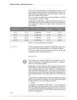
Since the flue temperature may lie below 100 °C when the system is
partially loaded, a chimney/flue is required which meets the require-
ments of DIN EN 13384-1: 2003-03 “Thermal and fluid dynamic calcu-
lation methods”. If it does not meet this standard, contact your
specialist heating company or chimney technician.
Another essential criterion is to achieve the correct conveying pres-
sure. This depends on three major factors.
C
HIMNEY
CHARACTERISTICS
The requirements for minimising the draught loss in the chimney are:
•
Good thermal insulation to avoid the flue gases cooling down too
quickly.
•
Smooth interior surface to reduce the flow resistance.
•
Chimney well-sealed to avoid outside air leaking in. Air penetra-
ting from the outside speeds up the cooling of the flue gases.
These requirements correspond to chimneys of the type according
to DIN EN 13384-1: 2003-03 “Thermal and fluid dynamic calculation
methods”.
Free-standing chimneys require particularly good insulation.
C
HIMNEY
DIMENSIONS
The system may only be connected to a chimney which has been di-
mensioned in accordance with DIN EN 13384-1, taking into account
the fuel planned and the expected load, and which meets local buil-
ding regulations for the installation site.
A chimney can only be designed with full knowledge of the on-site
conditions. This includes taking into account the following factors:
•
Location of the house
– Surrounding hills/slopes
– Wind direction
•
Location of the chimney in the roof
– The opening of the chimney must be at least 0.5 m above the
highest edge of roofs with a slope of more than 20° or at least
1.0 m higher than roof surfaces which slope at 20° or less.
•
The effective height of a chimney is measured from the entrance
into the flue to the end of the chimney.
C
ONNECTING
THE
BOILER
TO
THE
CHIMNEY
The boiler must be connected to the flue with a connecting piece
which is as short as possible, at an angle which is less than 30-45° to
the chimney. You should aim for a connecting piece with a maximum
length of 1 m using just one fitting.
Every additional fitting results in a greater pressure loss in the ex-
haust path and should thus be avoided. The same is true for overlong
connecting pieces. If, for constructional reasons, they have to be
When planning the flue system, a flue calculation based on DIN EN
13384-1 must be performed by authorised specialists.
Содержание Compact 100
Страница 1: ...hdg bavaria com HDG Compact 99 200 Operation Manual ...
Страница 2: ......
Страница 162: ...12 Index 162 HDG Compact 100 105 150 200 Version 1 de HDG Bavaria GmbH Juli 2005 NOTICE ...
Страница 163: ......