


4 Planning and installation – Connections
38
longer than 1 m, they should be adequately insulated (at least 5 cm
of mineral wool or equivalent material) and, if possible, should be
fitted with an upward inclination.
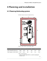
To compensate for irregularities in the flue draught of the chimney,
HDG Bavaria recommends installing an auxiliary air unit in the flue
pipe, or even better, in the chimney itself as shown in Figure 4/7 -
Connection to the chimney.
The following should also be considered:
•
The connecting piece may not protrude into the chimney.
•
If the system flue pipe has a larger diameter than the chimney, the
connecting piece must reduce to the diameter of the connection.
In this case, the connecting piece should taper as gently as pos-
sible.
•
Use bends rather than elbows; the radius of the elbow may not be
less than the diameter of the pipe.
•
The chimney should be vertical and straight, if possible without
kinks (take particular care in older buildings).
•
All of the cleaning and measurement hatches on the chimney
must be tightly sealed.
•
To reduce the entry of additional cold air, only attach one heat ge-
nerator per chimney.
•
To prevent dust from escaping, the flue pipe must be sealed with
heat-resistant silicone.
E
LECTRICAL
SYSTEM
The directives of 2006/95/EC (low voltage guidelines) must be fol-
lowed for the electrical connections to the system.
No electrical installations, such as power sockets, distribution boxes,
lights or light switches may be located in the fuel bunker. Any lights
must be suitable for use in areas at risk of explosion. The VDE regula-
tions for rooms with a risk of dust explosion must be followed.
1 Auxiliary air unit
2 Cleaning door
A) Chimney approx. 30° - 45°
B) Clearance at least 50 cm.
Figure 4/7 - Connection to the chimney
2
A
B
1
Содержание Compact 100
Страница 1: ...hdg bavaria com HDG Compact 99 200 Operation Manual ...
Страница 2: ......
Страница 162: ...12 Index 162 HDG Compact 100 105 150 200 Version 1 de HDG Bavaria GmbH Juli 2005 NOTICE ...
Страница 163: ......