


MAIN REMOTE CONTROL FUNCTIONS
11
ENGLISH
Main Remote Control Functions
IMPORTANT NOTE:
The AVR 645’s remote may
be programmed to control up to seven devices,
including the AVR. Before using the remote, it is
important to remember to press the
Input
Selector
button
4
that corresponds to the
unit you wish to operate. In addition, the AVR’s
remote is shipped from the factory to operate the
AVR and most Harman Kardon CD or DVD players
and cassette decks. The remote is also capable of
operating a wide variety of other products using
the control codes that are part of the remote or
by learning commands from other remotes. Before
using the remote with other products, follow the
instructions on pages 53-54 to program the
proper codes for the products in your system.
It is also important to remember that many of
the buttons on the remote take on different
functions, depending on the product selected
using the
Input Selector Button
4
. The
descriptions shown here primarily detail the func-
tions of the remote when it is used to operate
the AVR.
0
Power Off Button:
Press this button to
place the AVR or a selected device unit in the
Standby mode. Note that when the AVR is
switched off this will turn off the main room
functions, but if the Multiroom system is activated,
it will continue to function.
1
IR Transmitter Window:
Point this window
towards the AVR when pressing buttons on the
remote to make certain that infrared commands
are properly received.
2
LCD Information Display:
This two-line
screen displays various information depending on
the commands that have been entered into the
remote.
3
Power On Button:
Press this button to turn
on the power to a device selected by pressing one
of the
Input Selectors
4
(except Tape).
4
Input Selectors:
Pressing one of these
buttons will perform three actions at the same
time. First, if the AVR is not turned on, this will
power up the unit. Next, it will select the source
shown on the button as the input to the AVR.
Finally, it will change the remote control so that
it controls the device selected.
The buttons labeled DVD, DMP and HDMI 1 are
each used to select either of two input sources:
• The first press of the DVD Button selects the
component connected to the DVD inputs. A sec-
ond press of this button selects the component
connected to the CD inputs.
• The first press of the button labeled DMP
selects The Bridge as the input. A second press of
this button selects the device connected to the
Tape inputs.
• The first press of the HDMI 1 button selects the
device that is connected to the HDMI 1 jack. A
second press selects the device connected to the
HDMI 2 jack.
In normal operation, the remote will revert to
controlling the AVR when no button is pressed
for 6 seconds. This allows the remote to automat-
ically return to control of important functions
such as volume, mute and surround mode selec-
tion after you have used the remote to control
another device. If you wish to change the length
of time that the remote operates another device,
or to have the remote remain active for control of
the other device (such as a DVD player or set-top
box) until you manually return control to the AVR
by pressing the
AVR Selector
5
, follow the
instructions on page 40.
5
AVR Selector:
Pressing this button will
switch the remote so that it will operate the AVR’s
functions. If the AVR is in the Standby mode, it will
also turn the AVR on.
6
AM/FM Tuner Select:
Press this button to
select the AVR’s tuner as the listening choice.
Pressing this button when the tuner is in use will
select between the AM and FM bands.
7
6-Channel/8 Channel Direct Input:
Press this button to select the device connected
to the
6-Channel Direct Inputs
or the
8-Channel Direct Inputs
(the input
available will depend on the selection 5.1 or
6.1/7.1 made in the surround mode setting,
see page 27 for more information).
8
Test Tone:
Press this button to begin the
sequence used to calibrate the AVR’s output levels.
(See page 27 for more information on calibrating
the AVR.)
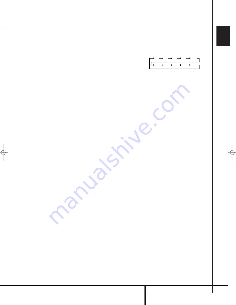
9
Sleep Button:
Press this button to place
the unit in the Sleep mode. After the time shown
in the display, the AVR will automatically go into
the Standby mode. Each press of the button
changes the time until turn-off in the following
order:
Hold the button pressed for two seconds to turn
off the Sleep mode setting.
Note that this button is also used to change
channels on your TV, VCR and Sat receiver when
the appropriate source is selected, using the
device
Input Selectors
4
.
A
Surround Mode Selector:
Press this but-
ton to select any of the HALL, THEATER surround
modes. Note that depending on the type of
input, some modes are not always available. (See
page 33 for more information about surround
modes.) Note that this button is also used to
tune channels on your TV, VCR and Sat receiver
when the appropriate source is selected using
the device
Input Selector
4
.
B
Night Mode:
Press this button to activate
the Night mode. This mode is available only with
Dolby Digital encoded sources, and it preserves
dialog (center channel) intelligibilty at low vol-
ume levels (See page 23 for more information).
C
Channel Select Button:
This button is
used to start the process of setting the AVR’s
output levels with an external source. Once this
button is pressed, use the
⁄
/
¤
buttons
E
to
select the channel being adjusted, then press the
Set
button
F
, followed by the
⁄
/
¤
buttons
E
again, to change the level setting. (See page
40 for more information.)
D
Dim Button:
Press this button to activate
the Dimmer function, which reduces the bright-
ness of the front-panel display, or turns it off
entirely. Press the button once to change the dis-
play to reduce the brightness by 50%, and press
it again within five seconds and the main display
will go completely dark. Note that this setting is
temporary; regardless of any changes, the display
will always return to full brightness when the
AVR is turned on. The blue illumination around
the
Standby/On Button
1
will always remain
at full brightness regardless of the setting to
remind you that the AVR is still turned on. The
blue accent lighting inside the volume control
will also remain at full brightness when the panel
is at 50%, but go out when the panel lights are
fully dimmed.
90
min
80
min
70
min
60
min
50
min
40
min
30
min
20
min
10
min
OFF
29851_AVR645_ENG 30/10/06 9:46 Side 11


