Harman Kardon AVR 645 Скачать руководство пользователя страница 61

PROGRAMMING THE REMOTE

61

ENGLISH

Programming the Remote

3. At the next menu screen press the 

⁄¤

Navigation Buttons

E

until 

RENAME

KEY

appears on the bottom line of the LCD

screen, as shown in Figure 77. Press the 

Set

Button

F

to continue.

Figure 77

4. The next display screen (Figure 78) is where

you select the device within which the key to
be renamed exists. Press the 

⁄¤

Navigation Buttons

E

until the name of

the base device appears. In our example, since
we want to rename a button within the DVD
device memory,

DVD

should appear in the

lower line of the LCD. When the desired device
name appears, press the 

Set Button

F

.

Figure 78

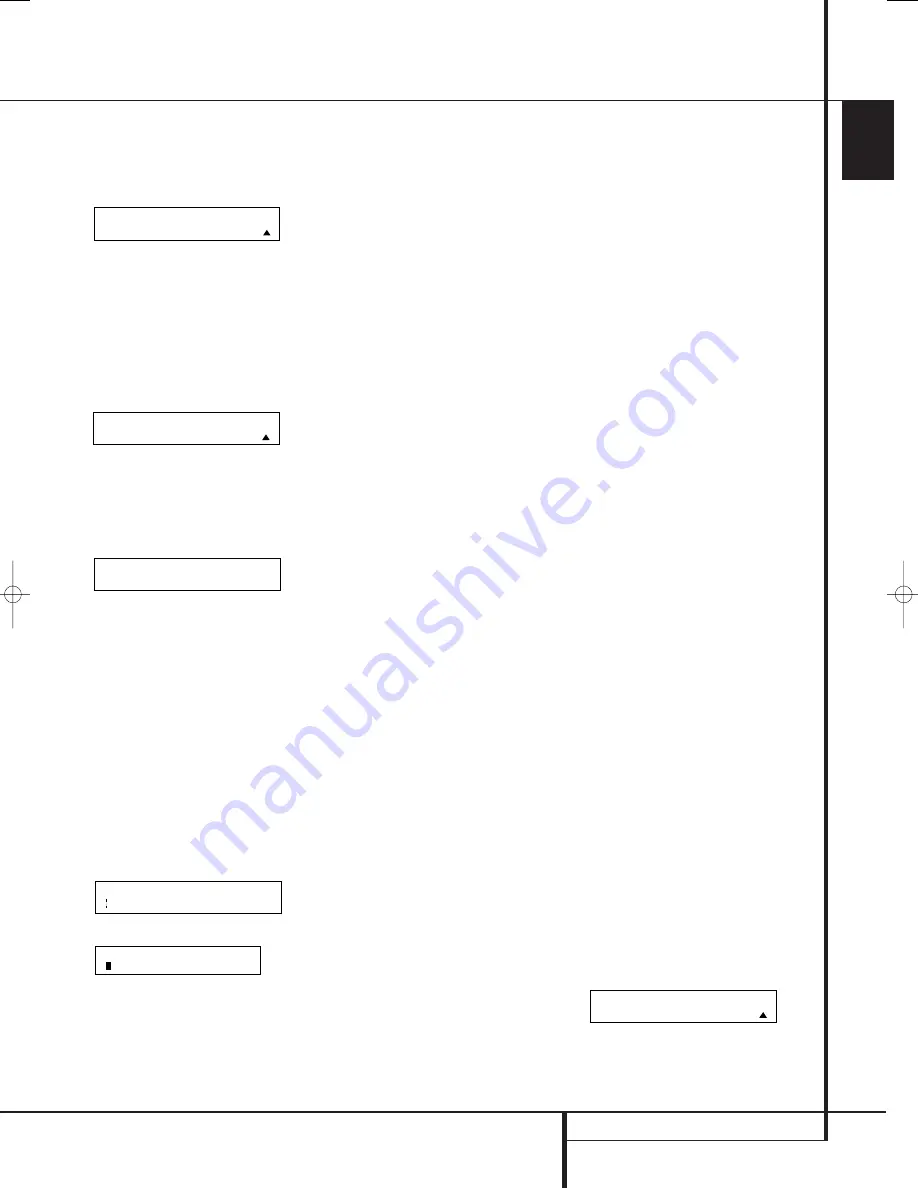
5. At the next menu screen you will select the

first button within the device to be renamed,
as instructed in the display shown in Figure
79. Select the button by simply pressing it on
the remote.

Figure 79

6. Depending on whether or not the button

pressed already has a named function within
the device selected, one of two things will
happen.

a. If the button to be renamed already has a

pre-programmed, or previously renamed
title in the remote’s memory, you will see
that name on the top line of the LCD
display, and a blinking block cursor will
appear on the far left side of the bottom
line of the display, as shown in Figure 80.

b. If the button to be renamed does not have

a function in the device selected, the top
line of the LCD screen will be blank, and a
blinking block cursor will appear on the far
left side of the bottom line of the display,
as shown in Figure 81.

Figure 80

Figure 81

7. To enter the new name for the key, press the

Numeric Keys

H

. The letters above the

numbered buttons indicate which letters or
symbols will appear when the button is
pressed during the renaming process. The first
press of the button will enter the first
character shown, subsequent presses of the
same button will change the display to the
other letters above that numbered key. For
example, since the first letter we need to
rename the Tone button to Zoom is a “Z,” so
you would locate the “Z” above the “9”
button, and press the button four times. The
first press shows a “W,” the subsequent
presses step through the other letters available
until the “Z” appears. Consult the table on the
previous page to see which characters are
available by pressing a particular button.

8. After you enter the first letter of the new

device name, there are three options for
entering the next character:

a. To enter a letter that requires a different

numeric key to be pressed, simply press
that button. The cursor will automatically
move to the next position and the first
letter accessed by the new button will
appear. Following our example, the next
letter needed is an “O,” so you would press
the “6” button once.

b. To enter a letter that uses the same

numeric key, you must first press the 

Navigation Buttons

E

to move the

blinking cursor block to the next position.
Then press the 

Numeric Key

H

as

required to enter the desired letter. This is
the way you would enter the second “O” in
the word ZOOM, and again for the letter
“M.”

c. To enter a blank space, press the 

Navigation Buttons

E

twice. The first

press will move the cursor to the right, and
the second press will move the cursor one
more space to the right, leaving a blank
space between the last letter and the next
one.

9. Repeat Steps 7 and 8 as needed to complete

entering the needed letters, numbers,
characters and spaces.

10. When the text entry is complete, press the

Set Button

F

. The new name will be

entered into the remote’s memory, replacing
the default name.

11. At this point you have two options:

a. If you wish to program an additional key

within the same device, press the 

Set

Button

F

as instructed by the bottom

line of the LCD display reading 

ANOTHER

KEY

. The remote will return to the

SELECT A KEY

menu option as shown in

Step 6. Repeat the instructions in Steps 6
though 11 to rename the next key.

b. If you have no additional keys to rename,

press the 

Navigation Buttons

E

once so that the menu screen displays

EXIT

on the bottom line of the display.

Press the 

Set Button

F

to return the

remote to normal operation.

Notes on Renaming Keys:

• Renaming a key does not change its function.

You may change the function of an individual
key by learning a new code into the remote.
See page 54 for more information.

• When a key is renamed it will only apply to the 

specific device selected in Step 4. The same key
may be renamed as needed for each individual
device with which it is used.

Resetting the Remote

Depending on the way in which the remote has
been programmed, there may be a situation
where you wish to totally erase all changes that
have been made to the remote and return it to
the factory defaults. You may do that by
following the steps shown below, but remember
that once the remote is reset, ALL changes that
have been made, including programming for use
with other devices, learned keys, macros, punch-
through settings and key names, will be erased
and any settings you had previously made will
have to be reentered.

To erase all settings and reset the remote to the 
original factory default settings and displays,
follow these steps:

1. Press and hold the 

Program Button

for

about three seconds while the message shown 
in Figure 25 appears in the remote’s 

LCD

Information Display

2

. Release the

button when the red light under the 

Set

Button

F

appears.

2. The remote’s 

MAIN MENU

message (Figure

26), will appear in the LCD display and the

Set Button

F

will remain illuminated in

red. Press the 

⁄¤

Navigation Buttons

E

until 

USER RESET

appears on the

bottom line of the LCD screen, as shown in
Figure 82.

Figure 82

M A I N   M E N U

U S E R   R E S E T

D I S C   S K I P

S E L E C T   A   K E Y

S E L E C T   A   D E V I C E

D V D

R E N A M E

R E N A M E   K E Y

29851_AVR645_ENG  30/10/06  9:46  Side 61

Содержание AVR 645

Страница 1: ...ENGLISH AVR 645 AVR 645 Audio VideoReceiver OWNER S MANUAL...

Страница 2: ...ypographical Conventions In order to help you use this manual with the remote control front panel controls and rear panel connections certain conventions have been used EXAMPLE bold type indicates a s...

Страница 3: ...s for use with portable recorders a Harman Kardon exclusive Two video recording outputs preamp out and a color coded eight channel input make the AVR virtually future proof with everything needed to a...

Страница 4: ...serviceable components inside this product Opening the cabinet may present a shock hazard and any modification to the product will void your guarantee If water or any metal object such as a paper cli...

Страница 5: ...e For example press this button to select Dolby modes and then press the Surround Mode Selector 9 to choose from the various mode options 6 Speaker Selector Press this button to begin the process of c...

Страница 6: ...he Digital Coax 4 Jack to an output Video 4 Input Output Jacks These audio video jacks may be used for temporary connection to video games or portable audio video products such as camcorders and porta...

Страница 7: ...rround Right Gray Surround Back Left Brown Surround Back Right Tan Subwoofer LFE Purple Digital Audio Orange Composite Video Yellow Component Video Y Green Component Video Pr Red Component Video Pb Bl...

Страница 8: ...sten to audio from the computer through the AVR 645 This connection is also used to connect a compatible computer to the AVR for firmware upgrades when available See page 43 for more information on pl...

Страница 9: ...es be made by a trained and qualified technician This jack may also link to a compatible computer to upgrade the software and operating system of the AVR 645 when appropriate upgrades are available Fa...

Страница 10: ...tal Mode Selector Logic 7 Mode Select Button Transport Controls Light Button Skip Up Down Buttons Stereo Mode Select Button DTS Neo 6 Mode Select Macro Buttons Disc Skip Button Preset Up Down Clear Bu...

Страница 11: ...ve for control of the other device such as a DVD player or set top box until you manually return control to the AVR by pressing the AVR Selector 5 follow the instructions on page 40 5 AVR Selector Pre...

Страница 12: ...II modes Dolby 3 Stereo or Dolby Digital Note that the Dolby Digital mode is only available with a digital input selected and the other modes only as long as a Dolby Digital source is not playing exc...

Страница 13: ...tton to begin the process of configuring the AVR s Bass Management System for use with the type of speakers used in your system Once the button has been pressed use the buttons E to select the channel...

Страница 14: ...optional infrared sensor that is connected to the AVR s Multi IR input jack We strongly recommend that the ZR 10 remote be used for the initial configuration and setup process for the AVR 645 A Power...

Страница 15: ...e button simply press the proper Numeric Keys G to select a station See page 51 for more information on the tuner N Memory Button Press this button to enter a radio station into the AVR s preset memor...

Страница 16: ...tistrand copper with an area greater than 2 mm2 Cable with an area of 1 5 mm2 may be used for short runs of less than 4 m We do not recom mend that you use cables with an area less than 1 mm2 due to t...

Страница 17: ...compatible with Based on the lowest level of HDMI among your sources the connections to the AVR should be made as follows HDMI 1 0 sources carry digital video and mul tichannel or 2 channel PCM audio...

Страница 18: ...lowing Scart to Cinch adapters or cables are needed Units for playback such as satellite receivers camcorders DVD or LD players need an adapter from Scart to 3 RCA plugs see fig 1 normal video devices...

Страница 19: ...with a SCART cable specific control signals apart from Audio Video signals will be fed to the TV These specific signals are With all video sources the signal for automatic input selection that switche...

Страница 20: ...mote location speakers in the same room as the AVR and connect the Multiroom Output jacks on the rear panel of the AVR to the audio input of the remote room amplifier Use the appropriate speaker wire...

Страница 21: ...Jack The AVR draws significantly more current than other household devices such as computers that use removable power cords For that reason it is important that only the cord supplied with the unit o...

Страница 22: ...One method of finding the optimal location for a subwoofer is to begin by placing it in the front of the room about 15cm from a wall or near the front corner of the room Another method is to temporar...

Страница 23: ...y modes Semi OSD and Full OSD When making con figuration adjustments it is recommended that the Full OSD mode be used This will place a complete status report or option listing on the screen making it...

Страница 24: ...entered up to a maximum of fourteen characters Press the Set Button F to enter the input name into the system memory and to proceed with the configuration process The audio input defaults for all sour...

Страница 25: ...V SYNC DELAY line and then press the Navigation Button EF until the desired amount of delay is applied so that the on screen video matches the audio When all configuration adjustments on this menu sc...

Страница 26: ...o HDMI when an HDMI signal is detected If a high definition input source is not HDCP content protected it may be output through the compo nent jacks otherwise it will be sent only to the HDMI outputs...

Страница 27: ...uration since some modes are only available when a full 7 1 speaker complement is present The full list of available modes is detailed in the surround mode chart on page 38 In addition you may also us...

Страница 28: ...lete expla nation of these modes is found on Page 38 The Dolby Digital EX mode is only available when the system is set for 6 1 7 1 operation by config uring the Surround Back speakers to Small or Lar...

Страница 29: ...he Texas Instruments DA 610 digital signal proces sor EzSet EQ eliminates the need for manual adjustment of speaker size crossover delay and output level settings while it adds the power of a multi ba...

Страница 30: ...the speakers in your system While this is happening the AVR is reading the signal to determine which speaker positions are active what type of speaker is present at each active position what the dist...

Страница 31: ...ontain an option to return to the NEAR FIELD EQ SELECT menu Figure 17g as well as the ability to return to the MASTER MENU If you are ready to proceed with the test make certain that the microphone is...

Страница 32: ...OFF is shown you are able to make any required adjustments that are available on that menu However you may change the setting to ON at any time to recall the settings established when EzSet EQ was las...

Страница 33: ...ont left right when LARGE is chosen no derived sound will be sent to the sub woofer output although in all cases the special low frequency effects LFE signals available on 5 1 or 6 1 digital programs...

Страница 34: ...he setting for a 10 inch 250mm driver activates a 30Hz subwoofer high pass filter The setting for a 12 inch 305mm driver activates a 20Hz subwoofer high pass filter The setting for a 15 inch 380mm dri...

Страница 35: ...will unlock the menu to allow changes When the delay time for all speaker positions has been set you may return to the master menu by pressing the Navigation Button EF until the cursor is pointing to...

Страница 36: ...then pressed to select OFF in the highlighted video The final option for tone adjustment using the menu system is to not use the internal test tone at all To do this simply use the Navigation Button...

Страница 37: ...he channel output levels for any input without changing the settings previously established for another When all changes to the Channel Output levels and the associated level trim settings have been m...

Страница 38: ...that are recorded with matrix surround or even with normal stereo mode creating separate rear left and rear right signals in any case The Pro Logic II mode creates compelling five channel surround sou...

Страница 39: ...Speaker Dolby Virtual Speaker technology uses a next generation advanced algorithm to reproduce the Reference dynamics and surround sound effects of a precisely placed 5 1 channel speaker system using...

Страница 40: ...t time that input was used The front panel Video 4 Inputs Optical Digital 4 Input or the Coaxial Digital 4 Input may be used to connect a device such as a video game or camcorder to your home entertai...

Страница 41: ...ic with music surround mode with any DTS NEO 6 mode or with Harman Kardon s exclusive Logic 7 Movie Mode to create a full range 5 1 channel or with Logic 7 and DTS NEO 6 even 7 1 channel surround sign...

Страница 42: ...speaker channels available in your system once the AVR locks to the digital signal you may select any surround mode or post processing option that is available based on the incoming data stream s pos...

Страница 43: ...ital 5 1 and DTS 5 1 programs A 2 tells you that separate front left and right signals are available but there is no discrete center channel signal This will be displayed for Dolby Digital bit streams...

Страница 44: ...s playing the letters in these indicators will light in response to the specific signal being received It is important to note that although Dolby Digital for example is referred to as a 5 1 system no...

Страница 45: ...seated The AVR s front panel controls may also be used to access a limited number of iPod functions Press the AM FM to play or pause the current track The Tuning Selector may be used to search in rev...

Страница 46: ...rease the level of the rears when you find it to be too low with specific surround modes If you wish to reset all the levels to their original factory default of 0dB offset press the Buttons E so that...

Страница 47: ...emind you that the unit is turned on If you wish to make other adjustments in the menu press the Buttons E until the on screen cursor is next to the desired setting or the BACK TO MASTER MENU line and...

Страница 48: ...ton F If you have no other adjustments to make press the OSD Button L to exit the menu system Full OSD Time Out Adjustment The FULL OSD menu system is used to simplify the setup and adjustment of the...

Страница 49: ...www harmankardon com or contact our customer service department Multiroom Setup Once the audio and IR link connections have been made the AVR needs to be configured for multiroom operation using the s...

Страница 50: ...ystem on or off even when the AVR is in the Standby mode in the main listening room IMPORTANT NOTE When an A BUS module is connected the AVR s Multiroom system must be turned on before the A BUS modul...

Страница 51: ...2 Within five seconds press the Numeric Keys H corresponding to the location where you wish to store this station s frequency Once entered the preset number will appear in the Main Information Display...

Страница 52: ...a specific Program Type PTY by following these steps 1 Press the RDS button until the current PTY is shown in the Main Information Display 2 While the PTY is shown press the Preset Up Down button or...

Страница 53: ...he remote s library at all you may still use the AVR remote to program most infrared controlled products by learning the commands from the product s original remote into the AVR remote The instruction...

Страница 54: ...member if the device turns off skip to Step 9 When all the codes for the device being programmed have been tried the instruction shown in Figure 34 will appear This means that the codes for the produc...

Страница 55: ...lay when the button that has just had a new code learned is pressed press the Navigation Buttons E so that the display shown in Figure 42 appears in the LCD display Press the Set Button F to open the...

Страница 56: ...es into the AVR remote using the process outlined on page 54 To begin the process start by selecting the brand of device as shown in Figure 29 Press the Navigation Buttons E until the brand name of th...

Страница 57: ...wer On followed by the Cable Box On followed by the selection of the Logic 7 mode To do that press the buttons in this order Power On 3 VID 2 TV 4 Power On 3 VID 3 Cable 4 Power On 3 AVR 5 Logic 7 O A...

Страница 58: ...To have the AVR s volume commands used when the TV device is selected follow these steps 1 Press and hold the Program Button for about three seconds while the message shown in Figure 25 appears in the...

Страница 59: ...ICE IN USE on the left side of the bottom line and the PUNCH THROUGH device In the example used the display to return the remote to default settings will appear as shown in Figure 68 Figure 68 Transpo...

Страница 60: ...on generates 7 After you enter the first letter of the new device name there are three options for entering the next character a To enter a letter that requires a different numeric key to be pressed s...

Страница 61: ...ic key you must first press the Navigation Buttons E to move the blinking cursor block to the next position Then press the Numeric Key H as required to enter the desired letter This is the way you wou...

Страница 62: ...to indicate that the setting has been accepted by the remote s memory 5 The remote s backlighting will now turn on whenever a button is pressed To revert to the original setting follow the four steps...

Страница 63: ...ction when Main No AC Power Make certain AC power cord is plugged Power Switch 1 is pushed into a live outlet Check to see if outlet is switch controlled Display lights but no sound Intermittent input...

Страница 64: ...NALOG DVD COAX 1 AUTO COMPONENT 3 ANALOG HDMI 1 HDMI 1 HDMI 1 DSP DOWNMIX HDMI 2 HDMI 2 HDMI 2 DSP DOWNMIX Tuner ANALOG AUTO COMPONENT 1 ANALOG CD ANALOG AUTO COMPONENT 3 ANALOG Tape ANALOG AUTO COMPO...

Страница 65: ...er 12 0 Feet Front Right 12 0 Feet Surround Right 12 0 Feet Surround Back Right 12 0 Feet Surround Back Left 12 0 Feet Surround Left 12 0 Feet Subwoofers 12 0 Feet Worksheet D System Defaults and Sett...

Страница 66: ...2 CD Tape Tuner The Bridge USB 6 8 Ch Direct Input Title Surround Mode Audio In Port Audio Auto Poll Video In Port Component Video Input Video Processing A V Sync Delay Record Output Auto Poll Input...

Страница 67: ...Version 1 1 General Power Requirement AC 220 240V 50Hz Power Consumption 120W idle 1180W maximum 7 channels driven Dimensions Max Width 440mm Height 165mm Depth 435mm Weight 19 9 kg Depth measurement...

Страница 68: ...250 Crossways Park Drive Woodbury New York 11797 www harmankardon com Harman Consumer Group Inc 2 route de Tours 72500 Ch teau du Loir France 2006 Harman Kardon Incorporated Part No ZKD3001HA00 R...

Отзывы: