


SYSTEM CONFIGURATION
33
ENGLISH
System Configuration
that will have on the speaker’s performance. If
you do not have access to the owner’s manual
for a particular speaker, you should be able to
obtain the needed information from the Web site
or customer service department of the speaker’s
manufacturer.
To manually adjust the speaker settings, go to
the
SPEAKER SIZE
menu by pressing the
OSD Button
L
on the remote and when the
MASTER MENU
(Figure 7) appears, press the
⁄
/
¤
Navigation Button
E
until the cursor
is on the
MANUAL SETUP
line and press the
Set Button
F
. When the
MANUAL
SETUP
menu (Figure 18) appears, press the
⁄
/
¤
Navigation Button
E
again until the
cursor is on the
SPEAKER SIZE
line and
press the
Set Button
F
.
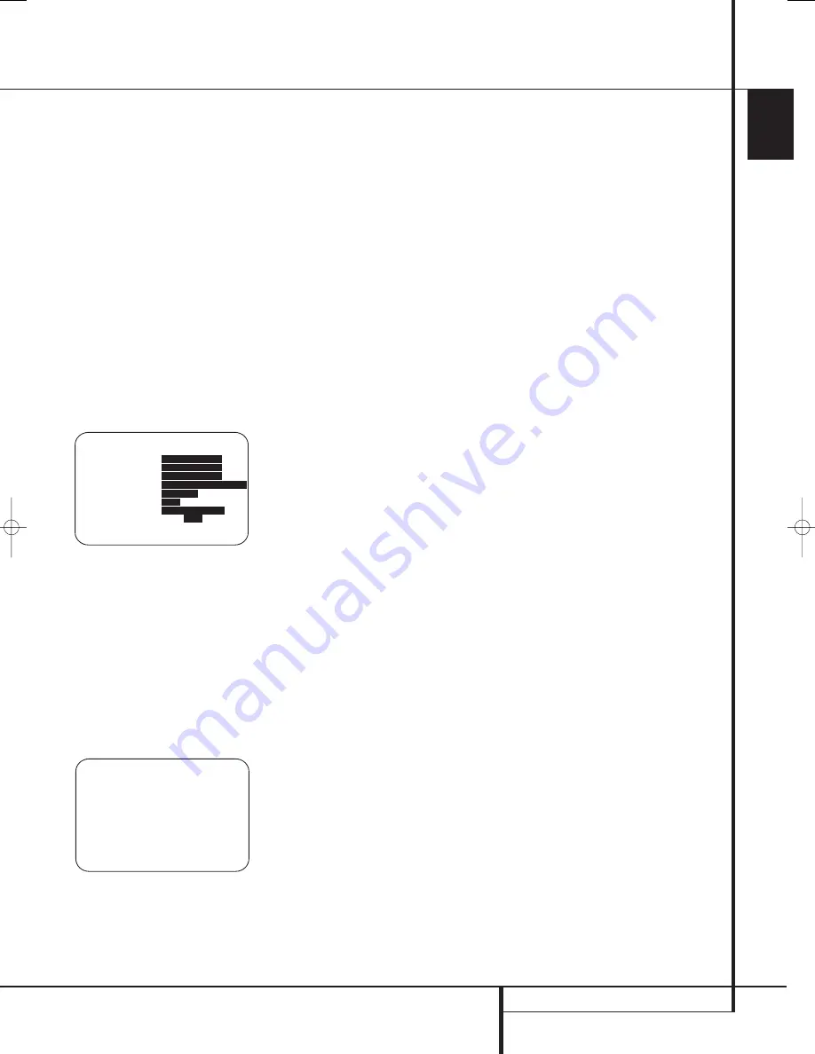
On the
SPEAKER SIZE
menu (Figure 19)
you will see a display of either the settings that
were established when EzSet/EQ was run, or the
factory default settings if you have not yet run
the automated system.
Figure 19
To change the setting for any of the four speaker
positions, press the
⁄
/
¤
Navigation Button
E
until the cursor points to the line where you
wish to make the change. Press the
‹
/
›
Navigation Button
E
to change the setting,
but note that when you do this for the first time
in the menu, a warning message (Figure 20) will
appear in the on-screen display reminding you to
rerun EzSet/EQ after you are finished with any
speaker configuration changes. This is necessary
to make any level output adjustments needed
after the setting changes so that the new
configuration will be properly integrated.
Figure 20
The warning message will remain for four
seconds and then the
SPEAKER SIZE
menu will return to the screen. At this point you
may change the settings to the “size” or
crossover for any of the four speaker positions
using the
Navigation Buttons
E
as shown
above. The information below details the settings
available for each of the speaker configurations.
At each of the four speaker position lines, you
have the option to set the speaker size and
crossover. Note that the “size” does not refer to
the speaker’s actual physical size, but rather to
the ability of the speaker to reproduce low-fre-
quency information. If your speakers at any
position are traditional full-range models capable
of handling the full audio spectrum, select
LARGE
. These speakers are called “large”
since the low-frequency drivers required to play
bass without strain or distortion are typically
eight to fifteen inches in diameter, in turn making
the speaker cabinet larger than those with small
(or no) low-frequency drivers. When the speakers
at a particular position are smaller frequency-
limited speakers that do not have the ability to
properly reproduce low-frequency sounds, select
SMALL
.
At all speaker positions except for the front
left/right speakers, you may also select
NONE
.
This setting tells the system that no speakers are
present at that position, allowing the AVR to
select the correct surround modes that are com-
patible with the number of speakers installed. For
example, in order to use the Dolby Digital EX,
Dolby Pro Logic IIx, DTS-ES, Logic 7/7- channel
and “7 Stereo” modes, you must have either
LARGE
or
SMALL
speakers entered as the
setting for the
BACK SURR
channels.
When
LARGE
is selected for any channel, a
full-range signal will be sent to the speaker out-
puts for that channel. For all speaker positions
except the front left/right, when
LARGE
is
chosen, no derived sound will be sent to the sub-
woofer output, although in all cases the special
low-frequency effects (LFE) signals available on
5.1 or 6.1 digital programs will always be sent to
the subwoofer output.
When
SMALL
is selected for any channel, you
may also enter a setting for the crossover fre-
quency at which sound is divided between the
frequency above which sound is sent to the
channel’s speakers and below which sound is
sent to the subwoofer. When configuring a
“small” speaker, choose the setting that has the
frequency closest to that of the lowest frequency
the speakers in question are capable of handling.
If one of the six available crossover points does
not match, select the one that is above, but
closest to, the speaker’s low-frequency limit.
When there are no speakers available at a
specific position, select
NONE
. When this option
is chosen for the Center or Side Surround
speakers, the sound that would normally be sent
to these channels will be split between the front
left and right speakers. Note that when your
system does not include Center or Surround
speakers, the use of Dolby Virtual Speaker as a
surround mode may provide a sound field that
simulates the presence of these speakers. (See
page 39 for more information on the Dolby
Virtual Speaker mode.)
Note that when
NONE
is selected for the Back
Surround speakers, the 6.1/7.1 channel surround
modes are not available. When this is the case
for your system you may wish to take advantage
of the availability of the unused amplifier channel
pair to power a second set of speakers in another
room. See page 33 for more information on
amplifier configuration.)
Once any desired changes have been made to
the speaker size and/or crossover, press the
⁄
/
¤
Navigation Button
E
to move the
cursor to any other line on this menu to make a
setting change, or go to the
BACK T O
MANUAL SETUP
menu and then press the
Set Button
F
to continue with overall
configuration.
LFE Low-Pass-Filter Setting
The
LFE L P FLT
line selects the frequency
setting below which sounds that may be avail-
able from a special low-frequency effects (LFE)
track are sent to the subwoofer. In most cases,
this setting will be set accurately by EzSet/EQ
but, should you wish to make a change from that
setting or the 120Hz frequency that is most
commonly used in the creation of LFE channels
by motion picture sound mixers, after making
sure that the
SPEAKER SIZE
menu (Figure
19) is on the screen, press the
⁄
/
¤
Navigation Button
E
so that the cursor is
pointing to
LFE L P FLT
. Press the
‹
/
›
Navigation Button
E
to begin the selection
process, and note that the warning message
(Figure 20) will appear reminding you to rerun
EzSet/EQ after all changes have been made.
When the
SPEAKER SIZE
menu returns to
the screen, press the
‹
/
›
Navigation Button
E
to make your selection. When the desired
setting appears, press the
⁄
/
¤
Navigation
Button
E
to move the cursor to any other line
on this menu where you wish to make a setting
change, or go to the
BACK T O MANUAL
SETUP
menu and then press the
Set Button
F
to continue with overall configuration.
* X - O V E R C H A N G E W A R N I N G *
S p e a k e r X - O v e r F r e q o r
S i z e h a s b e e n c h a n g e d .
P l e a s e r e - r u n E Z S E T / E Q
* S P E A K E R S I Z E *
→
F R O N T L / R :
S M - 1 0 0 H z
C E N T E R :
S M - 1 0 0 H z
S I D E S U R R :
S M - 1 0 0 H z
B A C K S U R R :
S M - 1 0 0 H z M A I N
L F E L P F L T :
1 2 0 H z
S U B M O D E :
S U B
S U B S I Z E :
1 0 i n / 2 5 0 m m
E Z S E T S E T T I N G S :
O F F
O N
B A C K T O M A N U A L S E T U P
29851_AVR645_ENG 30/10/06 9:46 Side 33


