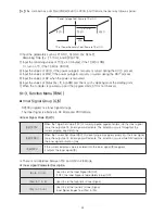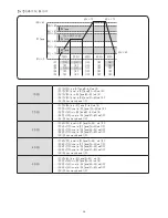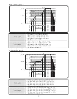
57
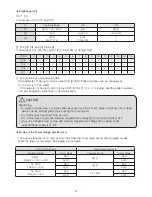
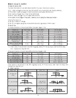
※ The Dead Band (DB) value of Alarm Output is default: EUS(0.5 %), Setting Range: EUS(0~100 %).
If AnTY is inactive (OFF), both AL-n and AnDB is not displayed.
●
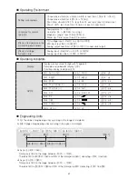
Types of Alarm
●
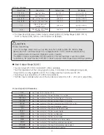
User Output (UO) Parameters
Alarm Code
Alarm Type
Default Value
Set Range
1, 9, 11, 19
High Limit Alarm
EU (100 %)
EU (0~100 %)
2, 10, 12, 20
Low Limit Alarm
EU (0 %)
EU (0~100 %)
3, 5, 13, 15
High Limit Deviation Alarm
EUS (0 %)
EUS (0~100 %)
4, 6, 14, 16
Low Limit Deviation Alarm
EUS (0 %)
EUS (0~100 %)
7, 17
High and Low Limit
Deviation Alarm
EUS (0 %)
EUS (0~100 %)
8, 18
High and Low Limit Range
Deviation Alarm
EUS (0 %)
EUS (0~100 %)
OFF
User Output (UO) is inactive (OFF).
ALM1〜4
User Output activates (ON) when the Alarm 1〜4 is active.
TS1〜TS5
User Output activates (ON) when the Time Signal 1〜5 is active.
IS1〜IS5
User Output activates (ON) when the Inner Signal 1〜5 is active.
PTEND
User Output activates (ON) when a program ends (if PTEND BIT is ON).
PROG
User Output activates (ON) during the program running.
FIX
User Output activates (ON) during the fixed control mode.
RESET
User Output activates (ON) when the reset mode.
HOLD
User Output activates (ON) when the hold mode.
WAIT
User Output activates (ON) when the wait mode.
MAN
User Output activates (ON) during the manual control mode.
PTUP
User Output activates (ON) during the ascending ramp segment.
PTDOWN
User Output activates (ON) during the descending ramp segment.
PTSOAK
User Output activates (ON) during the soak segment.
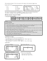
CAUTION
● Alarm Output Wiring
•Use a non-voltage contact switch such as relay when the controller supplies the needed voltage
(above 240 V AC) + resistance (above 1A) or voltage (above 30 V DC) + resistance load (above 1A).
•Use a bleeder resistor to draw more infinitesimal current, if required.
•The lifetime of relay is approximately 100,000 operations. If the load inductance is over the controller
specifications, the output may need a RC filter or diode to properly handle frequent relay switching operations.
•The User Output (U1~U10) for terminal ((U1~U10) is selectable.
•The U10 is disabled when the cooling output is a relay, if a controller is the Heating/Cooling model..
•Output will be a cooling regardless of U10. The cooling output has a priority over the U10.
•The setting of User Output (from U1 to U10) can be identical.
•The SGAL Input is activated when one of the four alarms is turned ON, if U5 ~ U10 is set to output SGAL.
◼
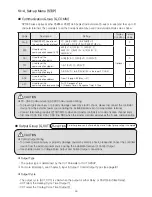
User Output Group (G.UO)
Содержание NP200
Страница 2: ......


