48
◼
PID Group (G.PID)
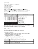
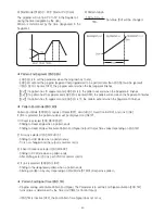
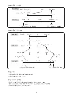
•When the control outputs reach the high limit value (OLH, OLL), they stop ordinary output action for
integral control and use the Anti-Reset Windup (ARW).
•When the setting is AUTO and the time for integral time (I) is not 0, the ARW is calculated automatically.
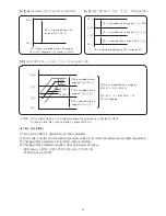
1) DV ≥ 0 & High limit output value
2) DV ‹ 0 & Low limit output value
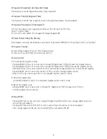
2) Continuous PID Control
The Continuous PID Control will output the current of 4~20mA.
The Cycle is 100ms time interval.
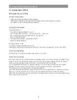
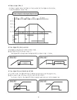
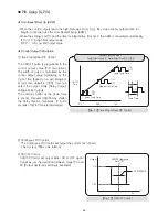
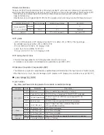
1) Time Proportional PID Control
The ON/OFF pulse is proportional to the
control output value (PID calculation).
The width of pulse is calculated by the
control output value multiplying by the
Cycle Time (based on a percentage of
its full scale, default is 100%). User can
select the output mode (Relay Output,
Voltage Pulse Output).
The control is better as the Cycle Time
is shorter. Frequent ON/OFF may shorten
the Relay lifetime. Generally, 10 to 30
seconds of Cycle Time is recommended.
●
Anti-Reset Wind Up (ARW)
●
Control Output Calculation
【Fig. 2.1】 Time Proportional PID Control
Control Output Pulse Width =
Control Output Value(%) × Control Output Cycle(CYCLE TIME)
0.0
100
50.0
ON
ON
ON
ON
OFF
OFF
OFF
OFF
Short Cycle Time
Medium Cycle Time
Long Cycle Time
Cycle Time
ON / OFF
Time
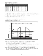
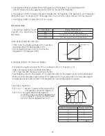
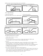
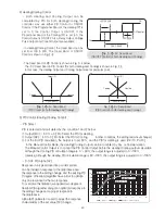
3) ON/OFF Control
ON/OFF Control will output either ON or OFF signal
Output as per the deviation between Target SV and
PV.(Output Hysteresis setting is available)
ON
OFF
Output
HYSTERESIS
PV
ON/OFF Operating
Point TSV
【Fig. 2.2】 ON/OFF Control
Содержание NP200
Страница 2: ......

