Overhaul
Installation and Service Manual
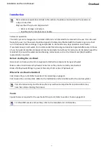
Reverse Shaft Shouldered Bush Replacement
With the reverse shaft [8] removed from the jet unit,
Press out the old bush using a suitable sized drift [10].
If the bush is hard to remove, apply light heat in the area of the bush to break the Loctite
®
bond.
Clean the bore of all old Loctite
®
and primer.
Apply a thin coating of primer 7471 to the whole surface of the bore and allow to dry.
Do NOT apply primer 7471 to the contact face of the bush [10].
Apply Loctite 680 to the bore in the tailpipe boss and to the front edge of the replacement reverse shaft bush
[10].
The bore in the tailpipe boss is to remain unpainted.
Loctite
®
primer 7471 must be used to refit the components otherwise the Loctite 680 will not
cure.
There are to be NO dry areas between the bush and the bore once the bush is fitted.
From the rear of the jet unit, press the bush into the bore.
Rotate the bush when fitting to distribute the Loctite
®
evenly.
Press the bush firmly home into the bore until the shoulder of the bush is flush with the edge of the intake
flange bore.
Wipe away any excess Loctite
®
and primer/activator.
Latch System Removal and Overhaul
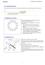
Disconnect the reverse cable from the reverse latch by removing nyloc nuts [53], flat washers [54] and
special washers [44] and also the cable clamp bracket [57] if the installation is left hand drive.
Remove the reverse duct. Refer to section: Reverse Duct Removal on page 9-6.
Disconnect the link actuator from the reverse crank. Refer to section: Reverse Link Removal and
Inspection on page 9-7.
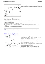
Remove the bolt [36] and bush [33] securing the brake rod end [26] to the cable mount plate [20].
If the hub retaining nut has not been removed, remove the hub retaining nut [37], special washer [34]
and spring washer [19]. Remove the latch assembly to the workbench.
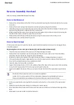
Mark the brake plates [46] so they can be reassembled in the same way.
Spread the brake plates [46] apart against the pressure of the spring [35], ensure that the detent plate
[23] is eased out of the detent groove in the brake rod and slide the brake rod [41] out of the assembly.
Remove the hub [47], and if required slide the brake plates [46] off the hub, remove the spring [35].
9-8
Содержание HJ212
Страница 1: ...HJ212 Installation and Service Manual R3A3 Jet unit Manual ...
Страница 20: ...Product Description Installation and Service Manual 2 6 ...
Страница 56: ...Commissioning Installation and Service Manual 6 4 ...
Страница 62: ...Fault Finding Installation and Service Manual 7 6 ...
Страница 82: ...Maintenance Installation and Service Manual 8 20 ...
Страница 137: ...Installation and Service Manual Appendix Notes 10 21 ...
Страница 141: ...Installation and Service Manual Appendix Notes 10 25 ...
Страница 164: ...Appendix Installation and Service Manual 10 48 ...
Страница 166: ......
Страница 169: ......
Страница 171: ......
Страница 172: ......
Страница 174: ...5 4 13 5 4 1307 0 3 453 5 4 4 4 05 50 64 8 53 5 50 5 5 3 454 0 8 50 0 5 54 3 5 0 5 8 50 0 5 11307 4 P 4 3 8 5 ...
Страница 175: ......
Страница 176: ......
Страница 177: ......
Страница 178: ......
Страница 181: ......
Страница 185: ......
Страница 186: ......
Страница 188: ......
Страница 195: ......
Страница 196: ......
Страница 197: ...Notes ...


