Installation and Service Manual
Maintenance
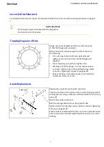
If a severe jam-up or impact has occurred, all parts of the steering system should be examined for damage.
This should include the remote system and the following items on the jet unit.
Steering shaft:
The steering shaft should be removed and checked for straightness, particularly at the crank end of the
steering shaft.
Tiller:
Check that the tiller is not bent and that the steering arm to steering shaft attachment bolt is secure.
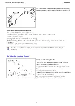
Crank and crank ball:
Check that the crank is not bent or worn. Replace if damaged. The crank ball should be checked for
excessive wear. The maximum clearance between the crank ball and the nozzle bush is 1.2mm (0.047ins).
Cotter:
Check that the tapered surface has no indentations. Replace if required.
Steering nozzle:
Check that the steering arm on the top of the nozzle is not bent. If any cracks are visible on the underside
of the steering arm, or in the web adjacent to the pivot boss, the nozzle must not be used and should be
replaced. If no faults are found, the underside of the steering arm should be crack tested using a dye
penetrant technique to prove the integrity of the steering arm before re-use.
Checking the Reverse Linkages
Failure of certain components can cause loss of stopping ability, or a sudden dangerous stop
while under way. Make sure that the following components are regularly checked:
Security of the cable mounts and attachments [53], [55] and [57].
Latch adjustment [45].
Freedom of the reverse shaft [8].
Security and correct torque on the duct-link bolt [25].
Freedom of movement of the duct [1].
Clearance between the duct and the splash guard [58].
Security of the splash guard bolts [59].
Security of the duct pivot pins [4].
Maintain the reverse system in good condition.
Refer to drawing: HJ21207003 Reverse Assembly.
Ensure the security of the cable connections to the controller and the latch.
Ensure that the cable mount on the bracket [20] remains tight.
Inspect the latch brake rod bush [33] and bolt [36] for signs of wear. Lubricate if necessary.
Check the condition of the split pin [14] securing the crank pin [12] to the reverse crank [11] and link
actuator [21].
Inspect the reverse latch hub [47] and the reverse shaft [8] connection for signs of wear. Lubricate as
necessary. Ensure that the hub retaining nut [17] remains tight.
Inspect the seal [15] around the reverse shaft [8] for any leaks.
Check for wear or binding on the bushes [9] and [10]. Lubricate the reverse shaft bushes every 30 hours.
Check the security of the cotter [16] and the split pin [14].
Inspect the link ball [22] for wear and make sure it is tightened to the correct torque. Refer to section:
Tightening Torques on page 10-28.
Ensure the o-ring [38] is in place.
Ensure the reverse duct pivot pins [3] are tight, and that there is no binding in the bushes [2] and [5].
The splash guard [58] should be checked to ensure it is secure and has adequate clearance on the
reverse duct [1].
Ensure the spring [18] is correctly fitted.
8-17
Содержание HJ212
Страница 1: ...HJ212 Installation and Service Manual R3A3 Jet unit Manual ...
Страница 20: ...Product Description Installation and Service Manual 2 6 ...
Страница 56: ...Commissioning Installation and Service Manual 6 4 ...
Страница 62: ...Fault Finding Installation and Service Manual 7 6 ...
Страница 82: ...Maintenance Installation and Service Manual 8 20 ...
Страница 137: ...Installation and Service Manual Appendix Notes 10 21 ...
Страница 141: ...Installation and Service Manual Appendix Notes 10 25 ...
Страница 164: ...Appendix Installation and Service Manual 10 48 ...
Страница 166: ......
Страница 169: ......
Страница 171: ......
Страница 172: ......
Страница 174: ...5 4 13 5 4 1307 0 3 453 5 4 4 4 05 50 64 8 53 5 50 5 5 3 454 0 8 50 0 5 54 3 5 0 5 8 50 0 5 11307 4 P 4 3 8 5 ...
Страница 175: ......
Страница 176: ......
Страница 177: ......
Страница 178: ......
Страница 181: ......
Страница 185: ......
Страница 186: ......
Страница 188: ......
Страница 195: ......
Страница 196: ......
Страница 197: ...Notes ...


