GSi TopDry Autoflow Скачать руководство пользователя страница 116

Chapter 10: Duct Installation

Installing the Fan Diffuser

The diffusers are used to effectively distribute airflow evenly throughout the plenum.

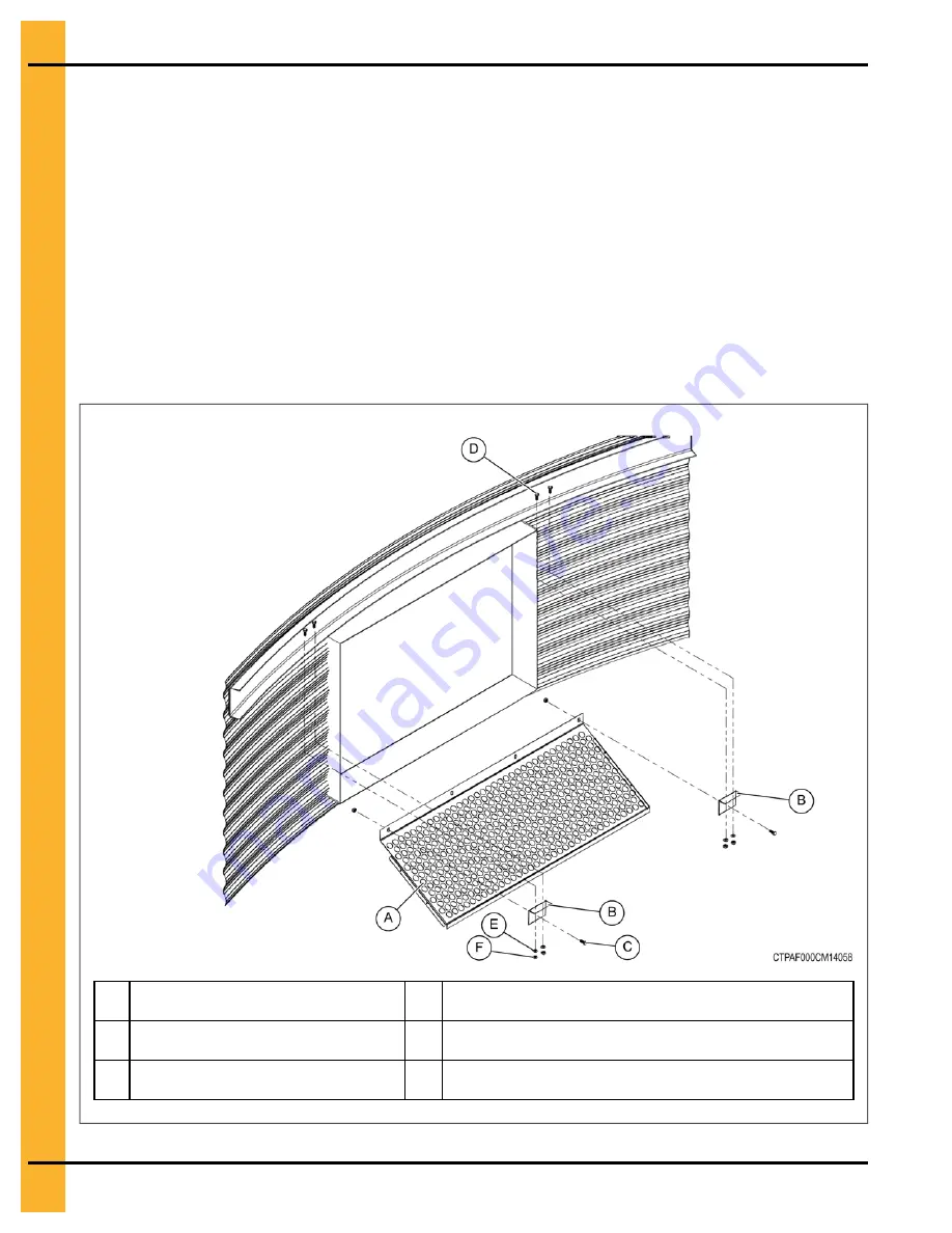
1. Install the diffuser hangers (B) to the end slots of the top plate (A) with the 1/4 x 1 in. self-drilling

screws (C).

2. Center the top plate (A) under the C-channel in front of the fan opening.

3. Mark and drill four 3/8 in. diameter holes into the bottom flange of the C-channel using the diffuser

hangers as a guide.

4. Install the top plate (A) and diffuser hangers (B) to the C-channel using 5/16 x 1 in. flange bolts (D),

5/16 in. flat washer (E) and 5/16 in. hex nuts (F).

Figure 10-1

Installing the top plate

A

Top plate (TD-100665)

D

5/16 x 1 in. flange bolt with sealing washer (S-10260)

B

Diffuser hanger (TD-100750)

E

5/16 in. flat washer (S-845)

C

1/4 x 1 in. self-drilling screw (S-7229)

F

5/16 in. hex nut (S-396)

116

PNEG-4936

36 Ft. TopDry Autoflow

Содержание TopDry Autoflow

Страница 1: ...TopDry Autoflow Models 36 FT DIAMETER Construction Manual PNEG 4936 Version 4 0 Date 07 15 20 PNEG 4936...

Страница 2: ...trations photos and specifications in this manual are based on the latest information available at the time of publication The right is reserved to make changes at any time without notice 2 PNEG 4936...

Страница 3: ...nd Nut Pairings 35 Hardware for 2 Post Sidewall Sheets on 4 in Corrugation Bins 36 Bolt Torque Specifications 36 Identifying Bolt Grades 37 Color Chart for Bin Hardware Buckets 38 Bolt Identification...

Страница 4: ...ing the Inside Cable Pulley 78 Assembling the Outside Cable Pulley 79 Chute Chain Assembly 81 Installing the Leveling Band Post 83 Installing the Leveling Band 84 Installing the Grain Temperature Sens...

Страница 5: ...ssories 129 Assembling the TopDry Access Door 129 Assembling the Access Door Platform 130 Assembling the Cross Over Platform 132 Door Placement 133 Two Ring Door Installation Instructions 134 Limited...

Страница 6: ...NOTES 6 PNEG 4936 36 Ft TopDry Autoflow...

Страница 7: ...equired Unqualified persons must stay out of the work area at all times Alterations must not be made to the equipment Alterations can produce dangerous situations resulting in SERIOUS INJURY or DEATH...

Страница 8: ...symbol indicates an imminently hazardous situation which if not avoided will result in serious injury or death This symbol indicates a potentially hazardous situation which if not avoided can result...

Страница 9: ...n result causing property damage personal injury or loss of life Carefully read all safety messages in this manual and safety signs on your machine Keep signs in good condition Replace missing or dama...

Страница 10: ...04 along with applicable European Direc tives for Europe Lock out power source before making adjustments cleaning or maintaining equipment Make sure all equipment is properly grounded ST 0027 4 Sharp...

Страница 11: ...before installing or servicing this equipment Installa tion and service must be performed by a qualified installer service agency or the gas supplier ST 0024 1 Install and Operate Gas Fired Equipment...

Страница 12: ...must be in place before and during operation Images of guards removed in this manual are for illustration purposes only Use caution when working around high speed fans gas burners augers and auxiliar...

Страница 13: ...off to purge products of combustion and to cool the components before entering Check regularly for any developing gas plumbing leaks Do not operate the dryer if any gas leak is detected Shut down and...

Страница 14: ...the fan heater drying plenum and ducts clean at all times In the event of a fire or suspected fire 1 Shut down the entire dryer 2 Turn off the fuel at the tank or supply valve 3 Shut off and lock elec...

Страница 15: ...PPE as needed Complete a permit to work and follow all permit required confined space entry procedures defined by the site manager Make sure that the area has been purged of any hazard ous products or...

Страница 16: ...ting equipment to ladders or platforms Do not go outside of the safety rails provided on elevated platforms Do not work at heights during high winds rain snow or ice storms ST 0056 1 Prevent Roof Dama...

Страница 17: ...ocation Decal No Decal Description Control Box DC 889 Danger High Voltage Chute Control Autoflow Only DC 1945 Warning Moving Parts Chute Control Autoflow Only DC 1948 Danger High Voltage Above access...

Страница 18: ...Description Control Box DC 1224 Danger High Voltage Control Box DC 1165 Danger High Voltage Located on duct access doors DC 973 Danger Automatic Equipment Located next to aeration system DC 969 Cautio...

Страница 19: ...rs DC GBC 1A Danger Keep Clear of Augers On bin door covers DC GBC 2A Warning Unload Instructions To replace a damaged or missing decal contact us to receive a free replacement GSI Decals 1004 E Illin...

Страница 20: ...n off sheet that can be used to verify that all personnel have read and understood the safety instructions This sign off sheet is provided for your convenience and personal record keeping Date Employe...

Страница 21: ...Roof instructions must be followed Roof instructions are included in this manual Ladders roof stairs roof handrails and other products are covered by separate instruction manuals Consult the appropria...

Страница 22: ...not fall over and cause injury If white rust or wet storage stain occurs contact the manufacturer immediately about ways to minimize the adverse effect upon the galvanized coating Guidelines for Cons...

Страница 23: ...eets loose to make the attachment of the stiffeners easier 8 Now re bolt the lifting brackets to the lowest ring in place thus far Continue ring additions by repeating Step 5 and Step 6 9 Add inside a...

Страница 24: ...roof Quantity will vary with individual systems IMPORTANT 1 Items I K M and O must be in this location between the first two stiffeners to the right of the fan for proper operation 2 Items I K and M m...

Страница 25: ...d at eye level H Ladder U Wet supply rotary switch optional I Plenum high limit sensor13 V Wet storage bin J Storage chamber platform W Control fan heater duct K Storage chamber rotary switch134 X Sec...

Страница 26: ...NOTES 26 PNEG 4936 36 Ft TopDry Autoflow...

Страница 27: ...The site must allow easy access for easy loading and unloading as well as provide additional space for future units 4 When selecting a bin site also consider the positioning of handling equipment fan...

Страница 28: ...on top of the compass 2 x 4 constructed earlier will enable you to set the top of the forms to match the top of the center stake 4 Check the form work with a transit to ensure a uniform elevation for...

Страница 29: ...Make sure the reinforcement rods are properly lapped by wiring 2 Place at least 2 in of compacted sand on the inside section of the foundation to provide a good base for the concrete and to protect ag...

Страница 30: ...lume system Exposed anchor bolt thread height B for 5 8 in and 3 4 in diameter anchor bolts are 3 in 7 6 cm and 5 in 12 7 cm respectively Overall anchor bolt length C for 5 8 in and 3 4 in diameter an...

Страница 31: ...adius start with one anchor bolt and work counter clockwise to locate one quarter of the anchor bolts then clockwise to locate another quarter of the anchor bolts Working off of the last anchor bolts...

Страница 32: ...dation Recommended pad thickness is 4 in minimum Front of pad must be perpendicular to bin wall Pad for heater not required CAUTION Fan pad and fan must be leveled and smooth for proper operation Vibr...

Страница 33: ...mmended pad thickness is 4 in minimum 3 Front of pad must be perpendicular to bin wall CAUTION The fan foundation and fan must be level and smooth for proper operation Improper leveling can cause vibr...

Страница 34: ...crushed stone of sand gravel mixture Backfill must be placed at 6 in lifts and well compacted The optional 4 rebar grid can be substituted for the wire mesh in most cases Place the 4 bars in the pad i...

Страница 35: ...sts the correct nut to use with each size of bolt Nut Part Number Nut Size Type Hex or Flanged Bolt Bolt Size Bolt Part Number S 396 5 16 YDP Hex 5 16 x 1 1 4 S 7483 Flanged 5 16 x 1 S 10260 S 3611 5...

Страница 36: ...x 1 42 5 16 x 1 20 3 8 x 1 2 10 3 8 x 1 22 3 8 x 1 42 5 16 x 1 20 3 8 x 1 2 Use 5 16 x 1 1 4 in for all stiffener to sidewall connections with splice and for all 5 gauge stiffener to sidewall connecti...

Страница 37: ...2 bolts are designated with a plain head and are not used in GSI grain bins Grade 5 Bolts Grade 5 bolts are designated by three slash marks on the head All 5 16 in diameter bolts are to be grade 5 or...

Страница 38: ...NA Orange 650 3 8 x 1 1 2 in bolt pre assembled with sealing washer S 7489 S 456 Yellow 3000 3 8 in hex nut S 9426 NA Dark Purple 2500 3 8 in hex flanged nut S 10261 NA Natural Clear 200 7 16 x 3 1 4...

Страница 39: ...to sidewall connection The color of the bucket lid is black A 1 437 in 3 64 cm C Grade 8 B 1 250 in 3 17 cm D Grade 8 2 Bolt S 7485 An S 7485 is a 3 8 x 1 in JS hex bolt with flanged head and without...

Страница 40: ...ollowing locations Use in all sidewall connections for 13 gauge through 10 gauge sidewall to sidewall sheets Color of bucket lid is grey NOTE Do not use to splice the stiffeners together on the flange...

Страница 41: ...of the holes it is necessary to use the correct orientation of the sidewall sheet during installation All the 4 00 in corrugation sidewall sheets have a top and bottom and must be placed correctly Fai...

Страница 42: ...Ga 16 Ga 17 Ga 18 Ga 18 Ga 18 Ga 18 Ga 20 Ga 11 14 Ga 15 Ga 15 Ga 16 Ga 16 Ga 17 Ga 18 Ga 18 Ga 18 Ga 18 Ga 20 Ga 12 14 Ga 14 Ga 15 Ga 15 Ga 16 Ga 16 Ga 17 Ga 18 Ga 18 Ga 18 Ga 18 Ga 20 Ga NOTE Fan en...

Страница 43: ...wall sheets with the overlap in the same direction Figure 5 2 Standard sidewall sheets Viewed from the outside of the bin A Vertical strip of caulk B 10 in 25 4 cm Horizontal strip of caulk 1 Apply a...

Страница 44: ...ay throughout until the ring is completed 3 Install the correct size bin bolts with the bolt head and its neoprene washer to the outside and the nut on the inside of the bin NOTE Do not tighten bolts...

Страница 45: ...auge 2 The first sidewall ring you assemble will be the top ring of the bin using the lightest gauge of sidewall 3 Check the various gauges of the bin with the color code chart and begin building acco...

Страница 46: ...NOTES 46 PNEG 4936 36 Ft TopDry Autoflow...

Страница 47: ...12 16 Ga Two Ring Stiffener 10 Ga to a Two Ring Stiffener 8 Ga Two Ring Stiffener 12 16 Ga to a Two Ring Stiffener 12 16 Ga Two Ring Stiffener 5 8 Ga to a Base Stiffener 5 8 Ga Two Ring Stiffener 10...

Страница 48: ...6 x 1 in grade 8 bin bolt with neoprene washer to install the stiffeners to the bin wall NOTE Make sure to have the bolt head and washer on the inside of the bin 4 Make sure the flanged nut is install...

Страница 49: ...18 Orange Top Stiffeners Use the following information to determine the differences between the types of top stiffeners The part numbers in the following table use an XX at the end of the number to r...

Страница 50: ...rs Call Out Part Number Description Length Available Gauges A FC 42062XX Two ring transition 94 594 in 240 cm 10 B FC 42057XX Two ring offset stiffener 94 594 in 240 cm 12 14 C FC 42075XX Two ring off...

Страница 51: ...ng information to determine the gauge of the splice needed to connect the stiffeners Figure 6 4 Stiffener splice Call Out Part Number Description Length Available Gauges A FC 42076XX Stiffener splice...

Страница 52: ...nd of the number to represent the gauge of the material Figure 6 5 Images of the base stiffeners Call Out Part Number Description Length Available Gauges A FC 42111XX Base stiffener 87 938 in 223 cm 5...

Страница 53: ...oot Call Out Part Number Description Height Base Plate Size A FC 42107 Base boot weldment for 14 through 8 Ga base stiffeners 6 188 in 16 cm 4 5 in x 7 in x 0 25 in 11 5 cm x 17 8 cm x 0 6 cm B FC 421...

Страница 54: ...y NOTE Only place bolts where holes in the stiffeners align with holes in the sidewall sheet One Ring Top Stiffener 16 Ga to a Two Ring Stiffener 12 16 Ga Reference the following information when conn...

Страница 55: ...Completed assembly NOTE Only place bolts where holes in the stiffeners align with holes in the sidewall sheet Two Ring Stiffener 10 Ga to a Two Ring Stiffener 8 Ga Reference the following information...

Страница 56: ...y place bolts where holes in the stiffeners align with holes in the sidewall sheet Two Ring Stiffener 5 8 Ga to a Base Stiffener 5 8 Ga Reference the following information when connecting a two ring s...

Страница 57: ...Completed assembly NOTE Only place bolts where holes in the stiffeners align with holes in the sidewall sheet Two Ring Stiffener 12 16 Ga to a Base Stiffener 12 14 Ga Reference the following informat...

Страница 58: ...mpleted assembly NOTE Only place bolts where holes in the stiffeners align with holes in the sidewall sheet Transitional Stiffener 10 Ga to a Base Stiffener 8 Ga Reference the following information wh...

Страница 59: ...ts where holes in the stiffeners align with holes in the sidewall sheet Base Stiffener 10 14 Ga to a Base Boot 10 Ga Reference the following information when connecting a base stiffener to a base boot...

Страница 60: ...the bin The gauges that span two columns represent a two ring stiffener of Rings of Side wall Stiff ener Base Ring Stiff ener Ring 2 Stiff ener Ring 3 Stiff ener Ring 4 Stiff ener Ring 5 Stiff ener R...

Страница 61: ...Intermediate Chute Bracket Installing the Floor Sheets Installing the Flashing Bolt Installing the Eave Flashing Installing the Eave Flashing Splice Installing the Chute Installing the Intermediate Ch...

Страница 62: ...et not counting the horizontal seam 2 Install the wall bracket A to the sidewalls and the stiffener B using 3 8 x 1 1 2 in flange bolts C 3 8 in sealing washers D placed between the wall bracket and s...

Страница 63: ...sheets 1 Install the C channels A to the wall brackets B in the top set of three holes using 3 8 x 1 in flange bolts C and 3 8 in hex nuts D Figure 7 2 Installing the C channel A C channel TD 100731...

Страница 64: ...ining the C channels A seams using 3 8 x 1 in flange bolts C and 3 8 in hex nuts D Figure 7 3 Installing the C channel splice A C channel TD 100731 D 3 8 in hex nut S 456 C 3 8 x 1 in flange bolt S 74...

Страница 65: ...and 3 8 in hex nuts E 2 Install the center collar cross channel F to the channel braces B using 3 8 x 1 in flange bolts D and 3 8 in hex nuts E NOTE Do not attach the center collar cross channel F unt...

Страница 66: ...enter collar at the center of the bin and raise it to the required height NOTE Height is measured from the bottom of the center collar to the foundation Figure 7 5 Center collar position G 11 ft 8 3 4...

Страница 67: ...e bolt S 7485 C C channel F 3 8 in hex nut S 456 1 Set the lower clip end of the rafter A or B on the C channel C and install the 3 8 x 1 in flange bolts E and 3 8 in hex nuts F 2 Connect the other en...

Страница 68: ...upper set of holes in the right hand rafter B and fasten using 5 16 x 1 in flange bolts I and 5 16 in flange nuts J 7 Install a short purlin H with the tab of the previously installed long purlin G us...

Страница 69: ...and 5 16 in flange nuts E IMPORTANT Make sure the purlins A and B are installed to the underneath side of the rafters C with the interior angle facing the center of the bin 3 Install the remaining pur...

Страница 70: ...the drying floor sheets D using 5 16 x 3 4 in self tapping screws C 4 Place the intermediate chute bracket E under the drying floor sheet D and align with the matching opening in the floor sheet 5 Att...

Страница 71: ...o be evenly spaced around the bin 2 Install the floor sheets A and C to the rafters using 5 16 x 3 4 in self tapping screws B NOTE Make sure that the self tapping screws B are not installed in the thi...

Страница 72: ...stall the eave flashing bolts 5 16 x 1 in flange bolts A through the top sidewall and tighten with the first 5 16 in hex nut B Figure 7 11 Installing the eave flashing bolt A 5 16 x 1 in flange bolt w...

Страница 73: ...flashing A to the eave flashing bolt B with the fender washers C and 3 8 in hex nuts D 3 Install the bottom of the eave flashing A to the flashing angle F with four 10 x 5 8 in self tapping screws E...

Страница 74: ...es as a single piece Bending the splice at the tabs C will break the eave flashing splice into three parts A and B Figure 7 13 Bending the eave flashing splice A Eave flashing splice middle piece TD 1...

Страница 75: ...E using 10 x 5 8 in self tapping screws D NOTE Field drill holes on the eave flashing E to install the eave flashing splice Also apply the tube caulk F in all the gaps Figure 7 14 Installing the eave...

Страница 76: ...using 1 4 x 3 4 in HHCS bolts C and 1 4 in hex nuts D IMPORTANT Do not tighten the first hex nut D down Lock the second hex nut D to the first hex nut D and make sure the chutes raise and lower FREEL...

Страница 77: ...3 4 in HHCS bolts C and 1 4 in hex nuts D IMPORTANT Do not fully tighten the first hex nut D Lock the second hex nut D to the first hex nut D and make sure the chutes raise and lower FREELY Figure 7 1...

Страница 78: ...ly using 3 8 x 1 in HHCS bolt C 2 Install the pulley A between the inside cable pulley bracket B using 3 8 x 1 7 8 in shoulder bolt D 3 8 in sealing washer E and 3 8 in hex nuts F Figure 7 17 Assembli...

Страница 79: ...n diameter holes K in the second ring 12 in O from the center of the hole on the horizontal seam 3 Install the pulley brackets F and G to the sidewall using 5 16 x 1 in flange bolts H and 5 16 in hex...

Страница 80: ...ulder bolt S 4749 K Field drill 3 8 in holes D 3 8 in sealing washer S 3558 L Stiffener E 3 8 in hex nut S 456 M Assembled pulley F Large pulley bracket TD 100038 N 9 3 8 in 23 8 cm G Small pulley bra...

Страница 81: ...able clamp S 4693 E 12 in when chutes are level closed position C Cable TD 100231 F Holes to connect the chain 2 Install the chains G to the lift plate A using the S hooks H and crimp the S hooks H NO...

Страница 82: ...that the end has not been cut open If this is found use the next link in chain G 7 The lift plate A must be approximately 12 in down from the cross channel when the chutes I are level closed position...

Страница 83: ...ing 5 16 x 1 in flange bolts B and 5 16 in flange nuts C 2 On the sixth and tenth hole of the floor sheet D install twelve leveling band posts A one in every third sheet using 5 16 x 1 in flange bolts...

Страница 84: ...er using 5 16 x 1 in flange bolts D and 5 16 in flange nuts E at the overlaps at every fourth hole NOTE The band sections connect to each other only at end most holes when completing the circle where...

Страница 85: ...r 2 set of leveling bands 7 Band sections per ring 12 Bays with 15 holes between posts A 6 3 16 in E 5 16 in flange nut S 3611 B 6 3 8 in F Leveling band post D 5 16 x 1 in flange bolt with sealing wa...

Страница 86: ...r 3 set of leveling bands 10 Band sections per ring 12 Bays with 22 holes between posts A 6 5 8in E 5 16 in flange nut S 3611 B 2 3 8 in F Leveling band post D 5 16 x 1 in flange bolt with sealing was...

Страница 87: ...umber 4 set of leveling bands 13 Band sections per ring 18 Bays with 18 holes between posts A 12 3 16 in E 5 16 in flange nut S 3611 D 5 16 x 1 in flange bolt with sealing washer S 10260 F Leveling ba...

Страница 88: ...outer most leveling band post B using bolts C and nuts D 2 Make sure that the approximate height of the sensor bracket from the floor sheet rib is 8 1 2 in 3 Refer to manual PNEG 4901 for the wiring a...

Страница 89: ...now The center cone assembly comes as separate sections 1 Install the center cone sections A together using 1 4 x 5 8 in bolts B and 1 4 in nuts C to form the center cone assembly Figure 7 27 Center c...

Страница 90: ...nter cone assembly G to the rafter J using 10 x 5 8 in self tapping screws I Figure 7 28 Center cone assembly installation G Center cone assembly J Rafter H Center collar K Center cone stiffener TD 10...

Страница 91: ...dge Filling the bin above this point creates excessive internal pressure and can cause swelling and eventual failure of the roof 1 After completing the assembly of the TopDry floor begin with the cent...

Страница 92: ...center support height will ease roof erection Figure 8 1 Center support A Bin height C Center support pole B Bin diameter Bin diameter ft Height using one ring of 4 in corrugated sidewall A 36 13 ft...

Страница 93: ...ree center collar A pieces together using 5 16 x 1 in flange bolts B and 5 16 in flange nuts C 2 This center collar A will be the upper center collar for the 36 ft diameter roof assembly Figure 8 2 As...

Страница 94: ...t channel 1 The intermediate center collar H is assembled from three pieces 2 Assemble the three intermediate center collar pieces H together using 5 16 x 1 in flange bolts B and 5 16 in flange nuts C...

Страница 95: ...installation direction B Roof panel CTR 0386G115 F Upper rib C Roof flashing CRP 4608 G Lower rib D 5 16 x 1 in flange bolt with sealing washer S 10260 H Intermediate center collar CRP 0795 E 5 16 in...

Страница 96: ...teps J when assembling roof panels B When assembling the roof steps J use 5 16 x 1 1 4 in bolts with a flat top washer on top of the slot and an extra neoprene washer L between the roof panels B and t...

Страница 97: ...611 O Roof channel CRP 4793 H Intermediate center collar CRP 0795 W Foam sealant Z collar S 10363 I Eave clip R 007 1 X Roof channel splice CRP 5262 J Roof step Y 3 8 x 1 in flange bolt S 7485 K Inter...

Страница 98: ...perly The end of roof flashing E must align with the splice in the intermediate center collar H to align properly for the timing of tabs with the roof panels Ensure to use flashing reinforcement angle...

Страница 99: ...asher V and 5 16 in flange nut U on the outside NOTE Adjust and tighten nuts U on straight end of slide rod T Figure 8 7 Installing the peak cap Sectional view through center collar A Center collar CR...

Страница 100: ...5 Install the hinge leaf B to the manway cover G and secure all four 5 16 x 1 in flange bolts C and 5 16 in flange nuts H Install the manway assembly to the hinge base A and secure with two 5 16 x 1...

Страница 101: ...5 16 x 1 in flange bolt with sealing washer S 10260 J 10 24 lock nut S 2010 D 10 24 x 5 8 in long bolt S 2009 K 5 16 x 1 in flange bolt with sealing washer S 10260 E Handle ACD 4513 L Manway roof pan...

Страница 102: ...counted up the required distance as described in the Table 8 1 page 102 install the appropriate brackets NOTE Do not install roof step A at a roof ring C location NOTE The last roof ring C pipe will n...

Страница 103: ...oof panel rib 4 Install a 5 16 in flange nut D to each roof ring clip C NOTE Do not tighten hardware until all roof ring sections B have been installed Figure 8 10 Installing the roof ring A 5 16 in x...

Страница 104: ...light crown NOTE Roof ring expansion bolts can become dislodged from the roof ring during the life of the bin due to the influence of wind or other factors If one expansion bolt is dislodged the entir...

Страница 105: ...the roof panel rib equally spaced for the top band clips A 3 Install the band clips A on the roof panels E with the 5 16 x 1 in flange bolts C and 5 16 in hex nuts D 4 Install the perforated center b...

Страница 106: ...NOTES 106 PNEG 4936 36 Ft TopDry Autoflow...

Страница 107: ...er Housing Assembling the Chain Guard Testing the Limit Switch Activation Attaching the Cable to the Turnbuckle Leveling the Discharge Chutes Chute Control and Cable Location The chute controller is m...

Страница 108: ...ner B 2 Field drill all six holes in the stiffener B using the stiffener mounting plate A as a template for hole locations making sure that the holes are drilled on the peaks of corrugation ridge 3 At...

Страница 109: ...housing A to the gussets B with six 5 16 x 3 4 in flange bolts C and 5 16 in flange nuts D 3 Field drill four holes in the bin sidewalls E through the four holes in the sidewall mounting brackets F m...

Страница 110: ...e bolts D through the sides and tightening with 5 16 in flange nuts E 3 Feed chain A from the large sprocket around the small sprocket and out through the back panel and up between the idler sprocket...

Страница 111: ...ams 2 After completing the wiring and before attaching the chain to the cable test that the sprocket travels from the open limit switch position to the closed limit switch position a Secure the tamper...

Страница 112: ...ute Controller Figure 9 5 Sprocket open and closed positions A Chute controller electrical box TD 101349 C Sprocket TD 101351 B Tamper switch TD 101463 D Limit switch TD 101465 112 PNEG 4936 36 Ft Top...

Страница 113: ...the bin through the sidewall sheet over the chute pulley at the bin eave and down to the chain turnbuckle that is connected to the chute controller 3 Set the turnbuckle D to the halfway point to allo...

Страница 114: ...to the chutes with chains The chute controller retracts the cable to close the chutes or extends the cable to open the chutes 1 Use the turnbuckle to adjust the chutes until they are horizontally leve...

Страница 115: ...talling the Fan Diffuser Installing the Top Elbow Duct Section Assembling the 44 in Duct Section Assembling the 32 in Expansion Section Assembling the Bottom Elbow Duct Section Typical Duct Assembly F...

Страница 116: ...ark and drill four 3 8 in diameter holes into the bottom flange of the C channel using the diffuser hangers as a guide 4 Install the top plate A and diffuser hangers B to the C channel using 5 16 x 1...

Страница 117: ...in hex nuts F 9 Place the side plates I and J on each side with the angle outward and install on the side brackets H with six 1 4 x 1 in self drilling screws C NOTE The corner bolt will need to be re...

Страница 118: ...outside 2 Install the small upper scroll duct B to the left top elbow duct C and the right top elbow duct D using 5 16 x 3 4 in flange bolts E and 5 16 in flange nuts F 3 Install the top elbow duct se...

Страница 119: ...uct mount brackets E and F using 3 8 x 1 in flange bolts I and 3 8 in flange nuts J 4 Tighten all the hardware Refer to the Bolt Torque Specifications page 36 5 Follow the same procedure to assemble t...

Страница 120: ...the corners of the panels A and B and assemble all the four panels together using 5 16 x 3 4 in flange bolts C and 5 16 in flange nuts D Figure 10 5 Assembling the top expansion section A Front and ba...

Страница 121: ...of the panel 4 Install the bulb seal H on top of the bottom expansion section J prior to sliding in the top section NOTE Make sure that the round half of the seal H is facing towards the outside Figur...

Страница 122: ...tallation 5 Slide the top expansion section E over the bottom expansion section J Figure 10 7 Assembling the 32 in expansion section E Top expansion section J Bottom expansion section 122 PNEG 4936 36...

Страница 123: ...bottom of left base elbow duct B and right base elbow duct C using 5 16 x 3 4 in flange bolts E and 5 16 in flange nuts F 4 Install the base elbow entrance panel H on the outside of the left base elb...

Страница 124: ...the sections of the 44 in duct assemblies A with the flange stiffeners B in between the duct section tabs using bolts C and nuts D Figure 10 9 Assembling the duct sections A Top elbow section C Bolt B...

Страница 125: ...uts D NOTE Only the top expansion section E is installed to the duct section The top expansion section E slides over the bottom expansion section G Figure 10 10 Assembling the expansion section to the...

Страница 126: ...bottom elbow section H to the bottom expansion section G Figure 10 11 Typical duct assembly A 44 in duct section G Bottom expansion section E Top expansion section H Bottom elbow section F Top elbow s...

Страница 127: ...s A to the bottom elbow duct B Fan legs D must set on the platform E 2 Mount the fan heater to duct using the appropriate face plate C Figure 10 12 Fan Heater mounting A TopDry fan heater unit D Fan l...

Страница 128: ...NOTES 128 PNEG 4936 36 Ft TopDry Autoflow...

Страница 129: ...ning and attach the top access door D and inside access door E to the Z frames B using 5 16 x 3 4 in flange bolts F and 5 16 in flange nuts G 5 Secure the 5 16 x 3 4 in flange bolts F to the doors wit...

Страница 130: ...h TD 101022 G 5 16 in flange nut S 3611 Q 5 16 x 3 4 in flange bolt S 6606 H Rear door catch TD 101020 R 5 16 in hex nut S 396 I 5 16 in flat washer S 845 S Handle gasket CRP 5003 J 5 16 in lock nut S...

Страница 131: ...cal angles H and handrails I and J on the platform support A using 5 16 x 3 4 in truss head screws M and 5 16 in hex nuts N 6 Install the handrail braces K to the platform vertical angles H and the si...

Страница 132: ...tform floor E to the platform support A using 5 16 x 3 4 in truss head screws J and 5 16 in hex nuts K 5 Install the platform vertical angles F and handrails G on the platform support A using 5 16 x 3...

Страница 133: ...g door can be used for bins with 13 rings and shorter heights Figure 11 4 Two ring door placement Viewed from outside of the bin A First ring from bottom of the bin C Door assembly B Second ring from...

Страница 134: ...t tighten until completing Step 4 4 Re install the inner door panels Q R and S at original locations Close latch bars J to lock panels in place Make sure that panels are fully seated over all bearing...

Страница 135: ...Chapter 11 Accessories NOTE Use WD 6242 for bins with 3 9 ring heights Figure 11 5 Standard Two ring door PNEG 4936 36 Ft TopDry Autoflow 135...

Страница 136: ...6039 Latch Bar 3 K WD 6037 Inner Panel Latch Right Hand 3 L WD 6038 Inner Panel Latch Left Hand 3 M WD 6040 Latch Bushing 6 N S 8648 1 2 in x 1 1 2 in Hex Socket Cap Screw 6 O WD 6079 Long Bearing Pi...

Страница 137: ...Chapter 11 Accessories NOTE Use WD 6244 for bins with 10 13 rings heights Figure 11 6 Heavy Two ring door PNEG 4936 36 Ft TopDry Autoflow 137...

Страница 138: ...Right Hand 3 L WD 6038 Inner Panel Latch Left Hand 3 M WD 6040 Latch Bushing 6 N S 8648 1 2 in x 1 1 2 in Hex Socket Cap Screw 6 O WD 6079 Long Bearing Pin 38 P WD 6125 Inner Panel Reinforcing Angle...

Страница 139: ...h outer door latch rod mount F Figure 11 7 Two ring door latch Callout Part Number Description Quantity A S 10185 5 16 x 1 1 2 in Flange Bolt 4 B S 10268 5 16 in Flange Nut 10 C S 4302 5 16 x 3 4 in T...

Страница 140: ...NOTES 140 PNEG 4936 36 Ft TopDry Autoflow...

Страница 141: ...dy for any claimant is set forth in this Limited Warranty and shall not exceed the amount paid for the product purchased This Warranty only covers the value of the warranted parts and equipment and do...

Страница 142: ...ulations which should be carefully followed in all cases Authorities having jurisdiction should be consulted before installations are made 1004 E Illinois St Assumption IL 62510 0020 Phone 1 217 226 4...

Отзывы: